Why is urethane casting ideal for complex geometries that traditional tooling cannot support?
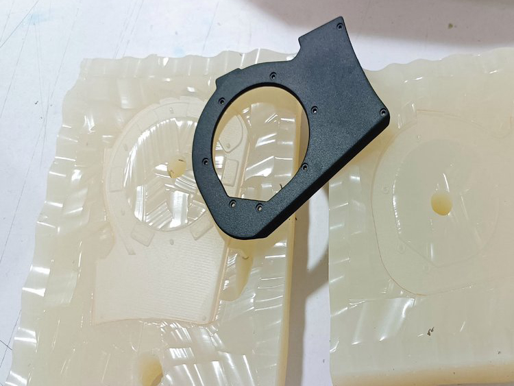
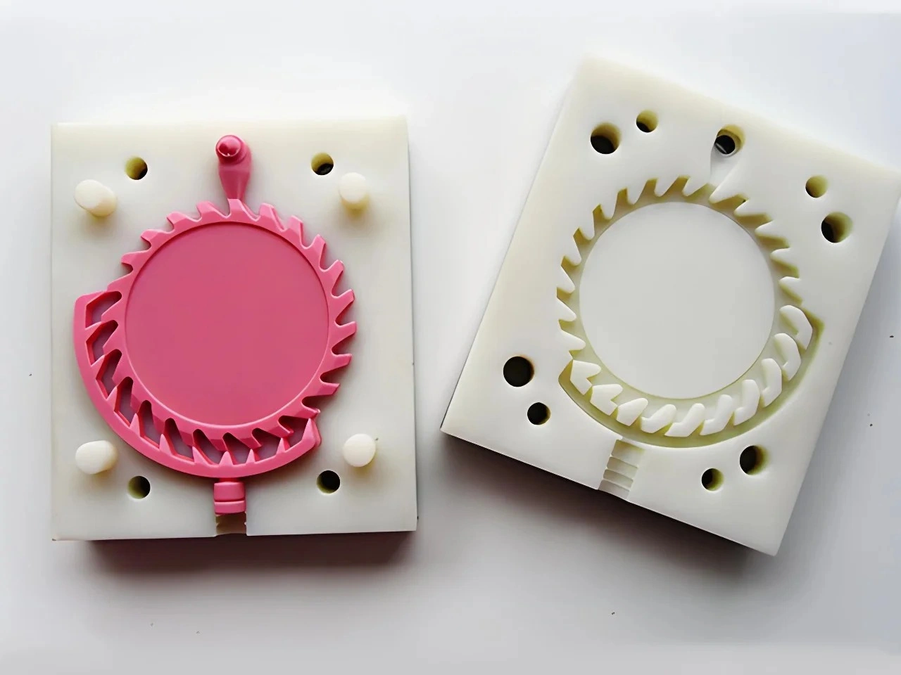
Urethane casting is well suited to some complex prototype geometries because a silicone mold can flex or use planned cuts around selected undercuts that would require slides, lifters or separate cores in rigid production tooling. The advantage is conditional. Trapped cavities, long extraction paths, thin silicone sections, fragile part features, poor venting and difficult trim access still require a deliberate mold and acceptance plan.
Geometry Release Decision Table
| Feature | Possible silicone strategy | Main risk | Evidence before lot release |
|---|---|---|---|
| External undercut | Controlled peel or planned cut | Mold tear, part distortion or seam | Repeated demolding trial |
| Deep hook/return | Loose mold piece or split change | Thin silicone ligament and long strain path | Mold-section and extraction review |
| Internal passage | Removable core or cast-and-join construction | Trapped core, air or blocked route | Core removal and passage test |
| Thin rib/clip | Local venting and supported demolding | Short fill, breakage or trim damage | Raw first-part inspection |
| Heavy boss beside wall | Section review and controlled cure state | Heat, shrinkage or dimensional bias | Conditioned part measurement |
Silicone Flexibility Replaces Some Hardware, Not Engineering
A rigid injection mold needs a straight release path or mechanical action for an undercut. Silicone may deform enough to clear the same feature during low-volume prototype demolding. That can reduce early tooling commitment while geometry is still changing.
Deformation must remain controlled. Undercut depth, return shape, part stiffness, silicone thickness and extraction length determine strain. A feature that releases once may progressively tear the mold or bend the part. The flexible-mold review should identify the intended deformation and replacement trigger.
Mold Splits and Planned Cuts Create Witnesses
A complex shape may need a multi-piece mold or a controlled cut through silicone after cure. These choices create seams, closure tasks and possible flash. Locate them away from datums, sealing faces, fine texture and primary appearance zones where geometry permits.
Define whether the witness remains, is trimmed or is cosmetically repaired. Repeated repair can change dimensions or texture across the lot. Approve a raw first casting before finish so mold evidence is not hidden by paint.
Fully Enclosed Geometry Needs a Core or Opening
Soft tooling cannot release a core that is physically trapped with no exit. Internal channels may need removable mold pieces, sacrificial cores, design openings, separate cast sections or another prototype process. Each option changes what the prototype proves.
Support and locate removable cores against defined references. Resin flow can move a weakly held core, changing wall thickness or blocking a passage. Inspect internal continuity with a gauge, mating component or another stated method rather than judging only the exterior.
Flow and Air Still Govern Complex Cavities
Thin paths, blind pockets and high points can trap air or stop filling. Choose the casting orientation, gates and vents around the actual geometry. A feature that is easy to demold may still be hard to fill; mold flexibility does not solve resin flow.
Gate and vent trimming needs access and an allowed witness location. First-part review should identify incomplete fill, bubbles, flash and local surface loss before the supplier proceeds. Corrections may require vent/gate changes, an added cut or a geometry revision.
Complex Features Must Survive Removal and Finishing
Long pins, thin clips, texture and sharp ribs can be copied from the master yet break or soften during extraction, trimming and coating. Identify which details affect the design decision and inspect them in both raw and finished states.
For flexible walls, state whether dimensions are measured free, fixtured or assembled. Use functional gauges when fit matters more than an unstable isolated coordinate. The production condition must be repeated later because injection or die-cast material, ejection and shrinkage differ.
Complexity Can Increase Recurring Labor
Flexible molds may avoid a metal slide but add manual loading, peeling, core handling, trimming and inspection to every part. Parallel molds do not remove downstream bottlenecks. Ask for accepted output by stage and price the actual demolding/finishing route.
A complicated silicone tool is justified when it closes product questions before permanent tooling. It is less attractive when each copy requires risky extraction or extensive repair, or when a direct print or assembled prototype can answer the same question sooner.
Production Tooling Still Needs Its Own Release Design
Geometry accepted in a flexible mold is not automatically ready for injection molding or die casting. Production DFM must establish draft, rigid parting, slides/lifters or cores, gates, cooling/thermal control and ejection for the selected process. Product engineering should approve changes where these requirements alter an interface or appearance zone.
The urethane design review documents what the prototype route proves and which flexible-tool assumptions cannot transfer. This keeps early geometric freedom useful without hiding the later hard-tool decisions.
Complex Geometry RFQ
Send controlled CAD/drawing, prototype purpose, internal passages, undercuts, appearance zones, critical interfaces, allowed seams, quantity, resin attributes, finish and inspection state. Ask for master route, mold splits/cuts/cores, gates/vents, demolding sequence, trim access, first-part gate and remake trigger.
Urethane casting supports complex geometry when flexible release is one part of a controlled process. Its value is reduced early hard-tool complexity, not freedom from flow, demolding, inspection or future production DFM.