
Split Bearing Housing: 80 Sets, Five Oval Bores
In an example record, five bores out of an 80-set lot of gravity-cast A356 bearing housings read 0.05 mm oval once the two halves were bolted, against a 0.03 mm limit on the drawing. Boring the bolted halves and aging the casting before the finish cut brought the next sets to 0.02 mm, with the insert unchanged.
The part is a split housing 120×95×70 mm, 420±30 g and a Ø60 H8 bore, all drawing targets. The alloy is A356 (AlSi7Mg) to GB/T 1173 ZL101A in the T6 temper. Its route runs melt and degas, pour, cut gate and riser, deburr, shot blast to Sa 2.5 under ISO 8501-1, mill the split faces, bolt the halves and bore, drill the flange holes, then final inspection.
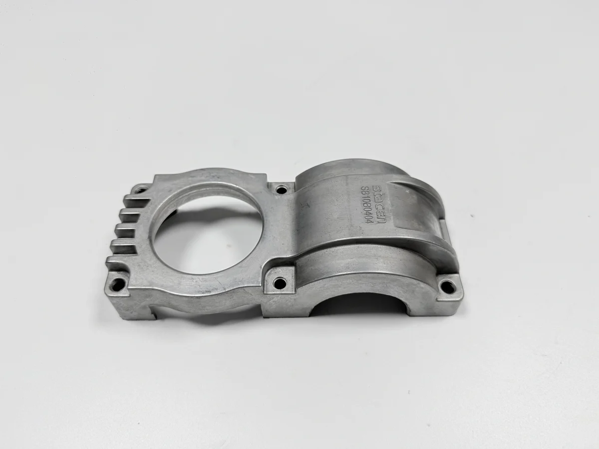
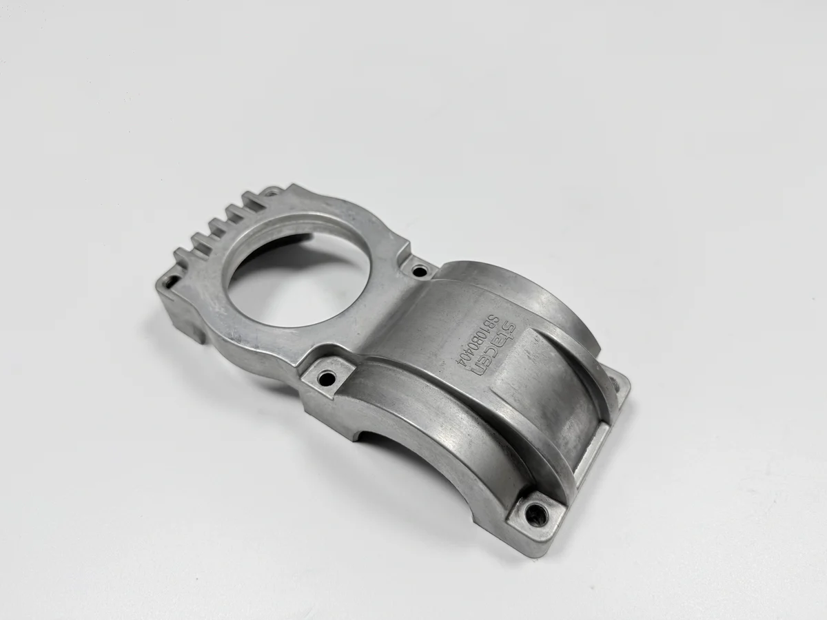
What did the 80-set run fail on?
Five of the 80 housings failed the bore check after bolting, and the reading was 0.05 mm, above the 0.03 mm limit. Ovality is the spread between the longest and the shortest diameter in one section, so a single caliper reading cannot show it.
The failure did not appear at the boring station. It appeared at the recheck with the split faces drawn together, where the bore moves as the bolts close. That recheck is a quoted station; a route that drops it saves a fixture and loses the only reading that matches the assembled part.
Where did the ovality come from?
Two forces meet at the bore. The T6 cycle leaves stress in a 5–8 mm wall that cools faster than the flange around it, and the clamp adds its own load while the bore is cut. A third force arrives with the bolts, since closing the split faces pulls a round hole out of shape.
The clamp lands on the four mounting ears and the flange, so its pressure crosses the casting before it reaches the bore. A sharp insert cuts a clean surface and cannot hold a bore that springs back when the jaws open and shifts again when the bolts close.
The two rows below are the example record, first lot and re-run.
| Run stage | Bores out of round (sets) | Ovality read (mm) | Limit (mm) |
|---|---|---|---|
| First lot of 80 sets | 5 | 0.05 | 0.03 |
| Re-run after bolted boring and stress relief | 0 | 0.02 | 0.03 |
How was the bore measured?
An internal micrometer, read at three points, catches what a caliper misses. A caliper takes one diameter, so a bore that is 0.05 mm out on one axis can still read correct on the other, and the oval passes the bench check.
The limit is 0.03 mm in every section from the front face to the back, applied to the bolted housing. A reading on the open halves is a setting check rather than a release check, because the bolts move the bore afterwards.
Which two changes fixed the bore?
The first change bored the two halves as one bolted body. The second added a stress-relief age at 155–165 °C for 4–6 h, a typical range pending foundry sign-off, between the rough and the finish cut.
Bolting before boring adds three stations that a split route does not carry on paper: bolting, boring, then unbolting and rechecking. The cost gap against boring each half sits in those three stations, and bolting is the only way the half-round seat and the bore share one axis.
What did the recheck read?
On the bolted housing the re-run read 0.02 mm, inside the 0.03 mm limit, taken with the same gauge at the same three points. A reading with the jaws closed would not compare.
Other features release on their own gauges, and the CMM report carries the coaxiality callout at 0.05 mm. The list below is what a first-article report has to name.
| Feature | Target (mm) | Allowed (mm) | Gauge |
|---|---|---|---|
| Bore diameter | Ø60 H8 | H8 limits as drawn | Internal micrometer |
| Bore ovality | 0.03 | 0.03 max, bolted | Internal micrometer, three points |
| Split face flatness | 0.05 | 0.05 max | Surface plate and feeler |
| Seat to bore coaxiality | 0.05 | 0.05 max | CMM |
| Flange holes 4×Ø9 | Ø0.3 position | Ø0.3 max | Go/no-go gauge and trial fit |
What does this case not prove?
The case proves one chain: five oval bores in an 80-set lot came back to 0.02 mm after bolted boring and a stress-relief age, read on the bolted housing. This case does not prove the yield of a whole production batch, because one lot, one mold and one boring setup are the entire record.
Service condition sets the boundary. The housing sits indoors in oil mist and vibration, so a part that runs outdoors or carries a reversing load falls outside this record. Sand-cast aluminum and cast iron stay open when the wall goes thicker or the lot goes small, and the route comparison between them starts from the bore and the split face.
The same pattern shows up in other cast-and-machined parts. A hinge program that ran casting and CNC in one order holds its fit by fixing the datum before either step. Send the drawing with the bore, the split face and the mounting face marked, plus the lot size, and a quote can separate the bolted boring and the stress-relief age from the casting itself.