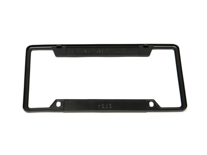
Auto Diecasting for Automotive Parts: From Alloy and DFM Review to Repeat-Order Validation
Auto diecasting is a good production route for an automotive part when the geometry gains value from integrated ribs, bosses, mounting planes, bores or protected passages, the order pattern can support tooling, and the buyer can validate the delivered part after machining and finishing. It is not automatically the right process for every vehicle component. A constant-section rail, a very low-volume evolving design or a highly loaded part with a different property route may fit extrusion, fabrication, forging or billet machining better.
The decision should be made on the finished component rather than on a casting blank. The buyer needs one linked review of aluminum alloy, filling and ejection, parting line, machining stock, datum transfer, porosity exposure, sealing, corrosion protection, inspection and repeat-order control. The metal casting service is the right starting point for comparing those routes, while the final approval remains tied to the project drawing, material definition, production volume and validation plan.
When Does Auto Diecasting Fit an Automotive Part?
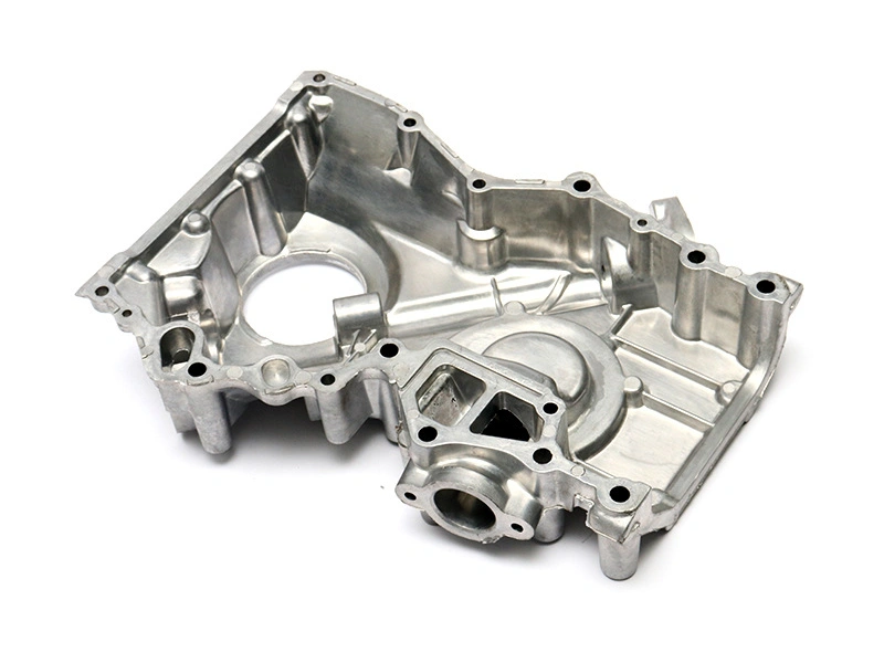
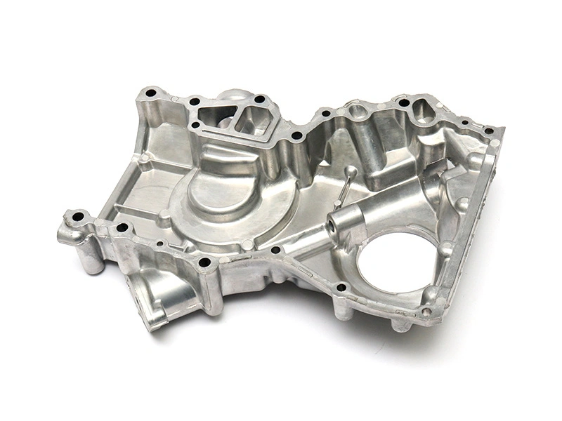
Auto diecasting fits best when the part benefits from making several functions in one aluminum casting. An electronics housing may combine a cover flange, connector openings, standoffs, cooling features and mounting ears. A motor-adjacent cover may combine a circular locating region with ribs and bolt bosses. A bracket may replace several fabricated pieces with one load-path structure. These benefits matter only if the interfaces remain accessible for trimming, machining, inspection and assembly.
Volume is a second gate, not the only gate. A stable design with recurring orders can spread die, trim-tool and process-development cost across many parts. A design still changing every few weeks may need CNC or a lower-investment prototype route first. The buyer should compare tooling, piece price, secondary operations, scrap exposure, maintenance and change cost over the expected program, not compare a casting blank with a finished fabricated assembly.
Part Situation | Why Auto Diecasting May Fit | Question Before Tooling |
|---|---|---|
Ribbed aluminum housing | Ribs, bosses and cover features can share one casting envelope | Do loads, sealing and machining datums support the proposed wall transitions? |
Connector or power-electronics cover | Openings, standoffs and mounting planes can be integrated | Which faces need final machining and which surfaces need masking or coating? |
Low-volume evolving bracket | Future volume may eventually justify a die | Would a prototype or machined route preserve needed design flexibility first? |
Constant-section rail | Only if die-cast bosses or cross features add enough value | Would extrusion or a formed section avoid unnecessary tooling complexity? |
A supplier should therefore state the route assumption in the quotation. “Automotive die casting” can describe a housing, a bracket, an interior hardware part or a thermal component with very different risks. The part envelope, critical features, annual demand, order-lot pattern and delivered condition decide whether the same phrase represents a sensible manufacturing plan.
How Should Buyers Screen Aluminum Alloys for Auto Diecasting?
Buyers should screen the alloy and casting process together. A380 and ADC12 are commonly considered for high-pressure die casting because complex production geometry and repeatability are part of the discussion. A356 is often considered in gravity, low-pressure or sand casting routes and may be supplied in a heat-treated condition when the project requires that route. The names are not interchangeable specifications, and an A356 result should not be used to release an A380 or ADC12 high-pressure die cast part without a defined equivalence decision.
The aluminum die casting service should review alloy choice with wall transitions, filling, solidification, machining, surface treatment and end-use exposure. For example, a housing with a pressure boundary may prioritize integrity and machining exposure; a bracket may prioritize section design, load evidence and distortion; a visible cover may add cosmetic and coating requirements. The correct alloy is the one supported by the complete part route and evidence plan.
Alloy Direction | Route Question | Buyer Evidence to Request | Do Not Assume |
|---|---|---|---|
A380 | Can the high-pressure route fill the geometry while protecting the required interfaces? | Specified grade, lot identity, trial results and project-selected mechanical or leak evidence | A handbook value alone proves the finished part |
ADC12 | Does the offered standard and process match the buyer's required chemistry and acceptance basis? | Named standard or customer specification, material record and delivered-condition definition | ADC12 is automatically identical to A380 |
A356 | Is gravity, low-pressure or another route better suited to the geometry and property plan? | Grade, temper if applicable, heat-treatment record and dimensional checks after processing | A356 is a drop-in high-pressure die casting substitute |
If the application includes dissimilar-metal contact, salt exposure or elevated temperature, the drawing should state the environment and joint design. Alloy selection by tensile strength alone can miss galvanic corrosion, coating adhesion, thermal movement, thread behavior or the effect of machining on a sealing land. Material certificates and representative tests answer different questions; the buyer should specify which one is required for release.
How Does Automotive Part Geometry Control Filling and Ejection?
Automotive die-cast geometry controls how metal reaches the cavity, how air escapes, how the casting solidifies and how the part leaves the die. Wall transitions should be reviewed for abrupt heavy sections, isolated bosses and long thin paths. Ribs can add stiffness without simply making the whole wall thick, but they also create local intersections that may cool differently. Deep pockets and internal windows need draft, core or slide access and a clear maintenance plan.
Parting line, gate, overflow and vent locations should be judged against function and appearance. A gate witness on a sealing flange or a vent remnant on a connector face creates downstream work. A hidden trim zone can be better, but only if metal flow and air evacuation remain feasible. Flash at a shutoff can interfere with assembly; a cold shut or incomplete fill can reduce the usable area of a structural or sealing feature.
Geometry Feature | Manufacturing Risk | Design or Tool Review |
|---|---|---|
Thick boss joined to a thin wall | Local shrinkage, sink-like distortion or uneven cooling | Use a supported transition and review feed, cooling and machining stock |
Long thin wall or window | Cold shut, incomplete fill or trapped gas | Check flow path, overflow, venting and the actual acceptance zone |
Deep pocket with an internal undercut | Ejection interference, slide wear or trapped flash | Confirm draft, core/slide access and a realistic trimming method |
Visible flange with fastener holes | Parting mismatch, gate mark, distortion or coating buildup | Separate appearance, flatness, hole position and finish requirements |
A CAD review can identify risks, but it does not prove a stable process. The buyer should receive a drawing-marked DFM response showing proposed parting, gates, overflows, vents, slides, draft assumptions and machining stock. When a feature is non-negotiable, its location and evidence method should be named before the tool design is frozen.
Why Should Mold Flow and Venting Be Reviewed Before Tooling?
Mold flow review belongs before tooling because an automotive housing can look simple from the outside while its internal ribs, bosses and wall transitions create a difficult filling sequence. Simulation can compare candidate gates, overflow locations, filling balance and likely hot spots. It is a design aid, not a certification of the final casting. The assumptions about alloy, temperature, die condition, cycle and boundary conditions must remain visible.
The mold flow analysis reference is useful when the buyer needs to ask how a supplier connected the proposed filling path to porosity, cold-shut and distortion risks. Review should end with decisions: change a rib transition, move a gate, add an overflow, protect a sealing face, alter machining stock or accept a documented development risk.
Venting also needs a part-specific boundary. An overflow or vent may reduce trapped air in one region but create trim or cosmetic work elsewhere. Vacuum assistance, where applicable, can address a defined gas-related risk but does not automatically prove leak tightness. The validation plan should identify the final pressure boundary, machining state, test method and acceptance limit.
Which Automotive Features Should Be Cast and Which Should Be Machined?
Use the casting to form the envelope, ribs, nonfunctional reliefs and accessible bosses; use CNC machining for interfaces whose dimension, location, flatness, roundness or surface texture controls assembly or sealing. Common machined features include bearing or locating bores, threaded holes, gasket lands, mounting pads and controlled connector interfaces. A drawing should identify whether the requirement applies as-cast, after trimming, after machining or after finishing.
The CNC machining route must be planned with the die and casting variation. A fixture cannot create a trustworthy datum if it locates on flash, a flexible wall or an unqualified ejector region. Cast pads or repeatable nonfunctional surfaces may establish the first setup, after which the machine creates the functional datums. Clamp force and support points should avoid hiding free-state distortion.
Feature | As-Cast Question | Likely Downstream Route | Evidence |
|---|---|---|---|
Gasket or sealing land | Can casting flatness and surface condition meet the pressure-boundary need? | Face milling with controlled stock and protected datum | Flatness, surface condition and defined leak test after machining |
Locating bore | Will casting position and roundness support the mating part? | Boring or interpolation from functional datums | Diameter, position, alignment and assembly check |
Threaded mounting hole | Can a core create a stable pilot without excessive wall or porosity risk? | Drill and tap, or another specified thread operation | Thread gauge, position, depth and torque requirement if specified |
Exterior rib | Does its cast shape provide the required stiffness and clearance? | Remain as-cast with controlled flash and edge condition | Profile, clearance and visual or functional inspection |
Post-machining should be treated as part of the product definition, not as a rescue operation. The CNC post-machining guidance can help frame questions about datums, fixturing and assembly fit. If a sample passes only after hand fitting, undocumented polishing or a fixture unavailable in production, that deviation must remain open before release.
How Can Buyers Control Porosity and Leak Paths in Auto Diecast Housings?
Buyers control porosity risk by mapping the pressure or sealing boundary, reviewing metal flow and air evacuation, limiting heavy-section traps, controlling machining exposure and selecting evidence for the actual failure question. Gas porosity, shrinkage-related voids, oxide-related discontinuities and cold shuts do not have the same mechanism or consequence. An indication away from a functional zone is not automatically a leak, while a connected path opened by drilling can be.
Risk is often revealed after machining. A casting can look sound on an outside face, then expose a discontinuity when a bore or gasket land is cut. Stock maps, section reviews and process controls should therefore be connected to the final machined boundary. If pressure retention matters, the buyer should define medium, pressure or vacuum, stabilization, duration, allowable leakage and sample plan rather than asking for a vague “air-tight” promise.
Risk Zone | Possible Mechanism | Risk-Selected Verification |
|---|---|---|
Machined sealing flange | Connected porosity is opened or the face lacks complete cleanup | Stock review, flatness/surface check and defined leak test |
Heavy boss or threaded port | Local shrinkage or drilling reaches an internal discontinuity | Wall/position check plus thread or leak evidence as required |
Long thin wall | Trapped gas, cold shut or incomplete fill weakens a functional region | Process review, visual/section method or imaging when justified |
Mounting flange near a gate | Trim witness, flash or distortion affects assembly flatness | Trim inspection, datum-based measurement and assembly check |
No single X-ray, CT, sectioning or pressure test answers every question. Internal examination can reveal a defined region, while a leak test evaluates a finished boundary under specified conditions. The buyer should select methods by consequence and correlate them only within the tested material, tool, machining and assembly state.
What Finish and Corrosion Details Need Definition?
Automotive aluminum parts may see humidity, road salt, cleaning chemicals, trapped water, thermal cycling and contact with coated or uncoated steel. The finish must be selected with the substrate, joint design and wear zones in mind. A coating can protect an exterior housing while creating trouble on a gasket land, grounding contact, threaded hole or press-fit bore if masking and thickness are not defined.
The post-process service should be asked to separate cleaning, deburring, blasting or conversion, coating, curing, masking and inspection. A visible surface may need a finish master; a hidden mounting face may need only corrosion protection. If dimensions are controlled after coating, the drawing must say so. Salt spray, humidity, adhesion, thickness and appearance tests answer different questions and require project-specific conditions.
Galvanic control can include an insulating washer, sealant, drainage path, coating continuity or a controlled bare-metal contact. These choices affect assembly, so the coating map should be reviewed with fasteners, gaskets, electrical grounds and thermal-contact lands. A general “black coating” description does not define protection or fit.
What Inspection Evidence Should Auto Diecasting Buyers Request?
Inspection evidence should follow the part's CTQs and the consequence of failure. A material record confirms grade and lot identity; a dimensional report confirms features in a named part state; a leak test confirms a defined boundary; an appearance master controls visible zones; and a process record connects the sample to a tool and route. A document title alone does not prove that the method represented the shipped condition.
The buyer can use the testing equipment overview to discuss CMM, gauges, material checks or other methods, but equipment availability is not a part-specific result. The inspection plan should state sample identity, cavity when relevant, datum scheme, method, acceptance limit, frequency and reaction to a nonconforming result.
Evidence | Question Answered | Definition Needed in the RFQ or Control Plan |
|---|---|---|
Material and lot record | Was the specified alloy and supplied condition used? | Grade, governing document, lot link and any required chemistry or property evidence |
Dimensional report | Are interfaces correct in the stated casting or machining state? | Datums, measurement method, part revision, sample identity and acceptance limits |
Internal-quality evidence | Does a defined zone contain a functionally relevant discontinuity? | Method, inspected zone, sample plan and disposition rule |
Leak or function test | Does the finished part meet the specified boundary or assembly condition? | Medium/load, pressure or vacuum, duration, fixture and allowable result |
Finish record | Does the delivered coating or surface meet the defined exposure and fit need? | Preparation, coating, mask, thickness/appearance method and sample state |
How Should Buyers Compare Auto Diecasting Suppliers?
Compare suppliers by the evidence they can produce for the actual finished part, not by a machine list or a generic automotive statement. Ask how they receive and control CAD and drawings, how they return DFM decisions, how they define alloy and tool state, how they plan CNC datums, how they investigate porosity and how they separate startup samples from production-intent samples.
The published EV die casting FAQ can help frame the difference between integrated geometry benefits and unproven vehicle-level claims. For a new auto diecasting program, ask the supplier to identify what is demonstrated by the sample, what remains a development assumption and which customer requirements would trigger broader validation.
A strong quotation also exposes exclusions. It should say whether trimming, CNC, deburring, coating, leak testing, inspection, packaging and tooling maintenance are included. A supplier can be technically suitable while a quote remains commercially incomparable because one bidder priced a casting blank and another priced a finished, inspected component.
What Should an Auto Diecasting RFQ Include?
Send the latest 3D model and 2D drawing with revision, units and precedence, plus the material grade or the property and corrosion constraints that keep the grade open. Mark datums, sealing faces, bearing or locating bores, threads, visible zones, electrical contacts, thermal lands and any feature that cannot move. State annual forecast, order lot, launch quantity, design stability and expected program duration.
Define the delivered state. Include trimming, CNC operations, deburring, coating, masking, cleaning, leak or function test, inspection reports, marking and packaging as applicable. If the part will be used in an EV or other high-consequence system, identify the actual component requirement without implying that a supplier has vehicle-level approval. A supplier should return an assumption register and a list of questions before tool release.
RFQ Input | Why It Changes the Auto Diecasting Quote | Buyer Action |
|---|---|---|
Controlled geometry and CTQs | Determines parting, slides, stock, fixture and inspection work | Identify revision, datums and non-negotiable interfaces |
Alloy and environment | Changes filling, machining, corrosion and finish choices | Name grade/condition or list constraints and approval path |
Volume and order pattern | Changes tooling economics, cavity strategy and capacity planning | Separate launch, pilot, normal lot and forecast quantities |
Finished operations | Changes cycle, fixtures, labor, inspection and packaging scope | Quote a finished part, not only an as-cast blank |
Validation and records | Changes samples, reports, tests and approval timing | State method, condition, limit, sample plan and change triggers |
Engineering Scenario: Aluminum Auto Diecast Housing With a Sealing Face
Consider a generic aluminum housing with a perimeter gasket land, two locating bores, several mounting bosses and an external rib field. The buyer wants one casting rather than a multi-piece fabricated assembly, but the gasket face must remain flat after machining and the bores must align with a mating cover. The image evidence in this article shows similar geometric features only; it does not establish this scenario as a customer project.
During DFM, the supplier maps the proposed gate and overflow away from the gasket land, checks the heavy boss transitions and identifies cast pads for the first machining setup. The buyer marks which outside ribs can remain as-cast and which mounting faces must be milled. The stock map then tests whether the sealing face can clean up without cutting into a variable wall or opening a connected discontinuity.
The trial plan records material identity, tool state, sample sequence and the final machining fixture. Inspection compares free-state and fixture-state results where distortion is a risk. A leak test, if the housing is a pressure boundary, is performed after the specified machining and surface operations. Approval applies to the recorded revision, material condition, tool, fixture, finish and test conditions only.
How Does Auto Diecasting Move From Pilot to Repeat Orders?
Moving from pilot to repeat orders requires more than a visually good first sample. The buyer and supplier should identify the accepted drawing revision, alloy and lot rules, qualified tool and cavity state, machining program, finish route, inspection plan, packaging and any open deviation. A pilot can demonstrate a route under limited conditions; it does not automatically prove every future lot or every tool change.
Repeat-order control should compare each new purchase order with the approved baseline. Changes in alloy source, insert, gate, vent, heat treatment, machining fixture, program, coating preparation, test method or packaging need an impact review. A focused recheck may be enough when the effect is isolated; a wider validation is justified when the change touches several CTQs. If PPAP or another customer submission is required, the customer requirement determines the content and release authority.
The practical approval decision is simple to state: authorize auto diecasting when the integrated geometry and expected order pattern justify the die, the chosen alloy and process address the part's actual functions, and the supplier can produce representative evidence through machining, finish and inspection. Keep the route open or choose another process when those conditions are not met. That decision protects the buyer from approving a casting concept that works only as a photographed blank.
FAQ