Sandblasting Die Cast Aluminum Parts: Media, Masking and Surface Acceptance
Sandblasting die cast aluminum parts is suitable when a defined mechanical surface treatment can clean or texture the casting without damaging thin fins, rounding critical edges, changing dimensions or leaving abrasive residue that disrupts a later coating. The purchase requirement should state the intended surface output and protected zones, not merely “sandblast all over.”
Blasting can make texture more uniform, remove selected oxide or residue and prepare an approved surface for another finish. It cannot repair shrinkage, cracks, deep pits, folds, dimensional error or internal porosity. It can expose those conditions by removing material or changing reflectivity, and the quality plan needs a reaction when that occurs.
The production route depends on incoming casting condition, media material and shape, particle condition, application energy, standoff, angle, dwell, line-of-sight access, masking, cleaning and inspection. No single pressure or media works for all aluminum castings.
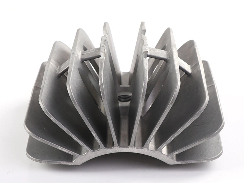
What Should Sandblasting Achieve on a Die Cast Aluminum Part?
The blast objective can be light cleaning, controlled texture, blending of permitted minor surface variation, removal of an existing finish or preparation for a specified coating. Each objective needs different evidence. A cosmetic texture can be released against a master, while coating preparation may require roughness, cleanliness and adhesion evidence from the complete finishing system.
Objective | Approval Evidence | Main Risk |
|---|---|---|
Uniform matte appearance | Production-intent appearance master and zone map | Over-blasting edges to hide local variation |
Remove light oxide or residue | Defined incoming condition and clean comparator | Smearing oil or embedding media |
Coating preparation | Approved roughness/cleanliness and coating validation | Treating abrasion as complete pretreatment |
Remove old coating | Substrate inspection and dimensional verification | Surface attack or retained old material |
Reveal substrate condition | Inspection and defect reaction plan | Misclassifying exposed defects as blast damage |
One process can have more than one objective, but the buyer should rank them. A route optimized for aggressive coating removal may be unsuitable for a fine decorative master. A route optimized for soft satin texture may not remove heavy oxide. Trying to satisfy conflicting goals through longer dwell usually increases geometry and variability risk.
How the Incoming Casting Condition Changes the Blast Route
Incoming castings should be inspected for gates and flash, release residue, machining oil, oxide, corrosion, burrs, prior coating, hand repair and exposed porosity. Blasting should not become an uncontrolled substitute for trimming, cleaning or defect acceptance. Oil can contaminate blasting media and be redistributed across later parts.
Cast skin responds differently from machined metal. Tool marks and fresh surfaces can become visibly different after blasting. Previously polished or repaired zones can create halos. The incoming boundary should state which surface variation is allowed before blasting and which parts must be held for casting or machining disposition.
Incoming Condition | Blast Planning | Required Upstream Action |
|---|---|---|
Release or machining oil | Avoid contaminating media | Qualified degreasing before blasting |
Gate/flash witness | Texture may reveal transition | Trim and blend under approved limit |
Oxide/corrosion | Define removal and inspection depth | Confirm substrate remains acceptable |
Machined zones | Protect or include intentionally | Mark dimensions and roughness needs |
Previous coating | Removal route may be aggressive | Identify chemistry and acceptable substrate change |
Visible pore or pit | Blasting may expose it further | Apply casting defect standard |
Coordination with aluminum die casting keeps the finish supplier from deciding structural casting acceptance through appearance alone. The active drawing should define allowed repair and inspection ownership.
How Buyers Should Choose Blasting Media
Media selection considers material, hardness, density, particle shape, size distribution, friability, contamination risk, desired texture and downstream process. Glass bead is often evaluated for a smoother peened or satin appearance. Angular aluminum oxide is more aggressive and cuts the surface more strongly. Ceramic and other specialty nonmetal media provide different durability and texture profiles. These descriptions are screening directions, not fixed process recommendations.
Media names alone are insufficient. New and worn media behave differently. Rounded particles can break and create sharper fragments; contaminated media can transfer oil, ferrous material or old coating. The supplier should control additions, replacement, separation, cabinet cleaning and prohibited cross-use.
Media Direction | Typical Screening Character | Buyer Risk to Check |
|---|---|---|
Glass bead | Rounded impact and satin appearance direction | Bead breakdown, embedded glass and edge peening |
Aluminum oxide | Angular cutting and stronger profile development | Overcut, roughness and dimensional change |
Ceramic media | Durable controlled texture options | Media grade, cost and residue compatibility |
Other nonmetal media | Application-specific cleaning or finish | Contamination, particle breakdown and coating compatibility |
Metallic media | High-energy cleaning in selected applications | Ferrous embedment and unsuitable aluminum surface effect |
Non-metallic blasting media provide context for contamination and surface-profile decisions.
Metal abrasive blasting adds different hardness, embedment and equipment considerations.
Specialty media for precision castings can address narrower finish goals. Every route still needs part-specific qualification.
How Pressure, Angle, Standoff and Dwell Should Be Controlled
Air pressure is only one input. Nozzle condition, media flow, particle mass, standoff distance, incidence angle, traverse speed and dwell determine energy delivered to the surface. A higher indicated pressure with low media flow can act differently from lower pressure with dense flow. Manual dwell can concentrate damage at corners and fin roots.
Buyers should approve a surface output and critical protection while the supplier controls validated settings. Production records can identify machine program, media condition and operator/station when risk requires it. Fixed universal values copied from steel blasting are inappropriate for thin aluminum castings.
A trial should cover the range of rack position, nozzle wear and normal media condition. One master made with fresh media and a new nozzle may drift as particles break down and the nozzle erodes. Periodic comparators or roughness trends detect loss of process center.
How Geometry Controls Coverage and Damage Risk
Thin fins, walls and webs can bend or vibrate under abrasive impact. Sharp edges can round. Deep pockets and close fin spacing create line-of-sight shadows, while attempts to reach them can over-blast exposed rims. Blind holes retain media. Threads and sealing lands can lose fit or roughness.
Feature | Blast Risk | Control Direction |
|---|---|---|
Thin cooling fin | Bending, edge loss and root overexposure | Support, low-energy trial, angle and dwell limit |
Deep pocket | Uneven coverage and trapped media | Multi-angle access and cleaning verification |
Sharp external edge | Rounding and appearance change | Edge exclusion or reduced exposure |
Thread/bore | Fit change and retained abrasive | Plug/cap and post-mask gauge |
Sealing land | Roughness and flatness damage | Fixture shield or no-blast zone |
Raised logo | Edge rounding and contrast variation | Appearance-master and controlled angle |
For fragile geometry, support fixtures can reduce vibration but also create shadow marks. The fixture contact and movement must be part of the approved sample. Inspect fin spacing, straightness and critical edges after blasting rather than accepting texture alone.
Which Areas Need Masking or No-Blast Zones
Mask or shield areas where abrasive impact would change dimension, surface function, electrical contact, seal behavior or appearance. These commonly include bearing seats, threads, precision bores, gasket lands, datum pads, identification marks and coating-free transitions. Masking can use plugs, caps, tape or fixture shields selected for blast resistance.
The drawing should dimension the no-blast zone and allowable transition band. “Protect the holes” does not state whether the chamfer, counterbore or first thread turn can be textured. A mask can erode, leak or shift during blasting, so production inspection should check both protected surface and boundary.
After mask removal, inspect for adhesive, damaged plugs, embedded grit and a sharp abrasive ridge. The route for machined casting features should identify which dimensions and gauges repeat after blasting.
How to Define Surface Texture and Roughness
Visual texture and instrumented roughness are related but not interchangeable. A surface can have similar Ra while looking different because peak shape, direction, reflectivity or waviness changed. Ra alone does not describe Rz, sharpness or cosmetic uniformity. Buyers should define the evidence that serves function.
For cosmetic parts, use production-intent masters with alloy, media, process date, zone, lighting, viewing distance and orientation controlled. For bonding or coating preparation, specify roughness parameters and method where technically relevant, along with coating validation. Measurement locations must have enough area for the instrument and avoid invalid edges or tight radii.
Texture Requirement | Control Method | Limitation |
|---|---|---|
Cosmetic uniformity | Approved master and surface zones | Photographs alone distort appearance |
Ra/Rz range | Defined instrument, cutoff and locations | One parameter may not predict coating behavior |
Directional texture | Probe direction and visual orientation | Random blasting may not create one lay |
Coating readiness | Complete pretreatment/coating trial | Roughness does not prove cleanliness |
Edge condition | Radius comparator or dimensional inspection | Flat roughness cannot represent edge loss |
No roughness value should be inferred from the supplied images. The actual specification must be tied to measured samples and the downstream requirement.
How to Validate Blasting for Powder Coating, Painting or Bonding
A blasted surface approved for bare appearance is not automatically ready for powder, liquid paint or adhesive bonding. Downstream processes may need a specific chemical cleanliness, profile, conversion treatment and time limit. The blast trial should therefore continue through the intended complete route before the substrate condition is frozen.
For organic coating, evaluate loose media, dust, oil transfer, roughness peaks, opened pores and edge condition before approved cleaning or conversion. Then verify coating distribution, cure, adhesion, appearance and service-specific evidence. An aggressive angular profile can increase apparent mechanical key while creating peaks that are difficult to cover. A smooth peened surface may look attractive but require different preparation for adhesion.
For adhesive bonding, the adhesive supplier's surface-preparation and contamination limits govern the process. Handle blasted bond zones with controlled gloves and do not touch, oil or package them with shedding material. Validate bond strength and failure mode after the maximum allowed delay, not only immediately after blasting.
Downstream Route | Blast-Related Evidence | Complete-Route Evidence |
|---|---|---|
Powder coating | Profile, dust, media and edge condition | Pretreatment, DFT, cure, adhesion and appearance |
Liquid painting | Clean texture and residue control | Primer wetting, intercoat, cure and finish |
Adhesive bonding | Bond-zone cleanliness and timing | Bond strength and specified failure mode |
Bare cosmetic finish | Master, roughness and handling | Corrosion/storage controls if required |
Conversion treatment | Compatible surface and no embedded residue | Approved chemistry response and coating validation |
If a downstream failure appears, preserve samples from before and after blasting and cleaning. Do not assume that rougher blasting will improve adhesion or that additional washing will remove embedded media. Test the interface that failed and change one controlled variable at a time.
How Media, Equipment and Maintenance Changes Should Be Controlled
Blast output drifts as media breaks down, nozzles wear, separators lose efficiency, filters load and fixture shields erode. Operators may compensate by slowing movement or increasing pressure, changing surface energy without a formal setting revision. Production controls should monitor the surface result and the equipment factors that influence it.
Media addition and discard rules should prevent uncontrolled mixtures of fresh and heavily fractured particles. Cabinets used for different metals, coatings or soils need segregation or validated cleaning. A change in media supplier, manufacturing lot or nominal grade can require sample comparison even when the general media name stays the same.
Change | Potential Effect | Review |
|---|---|---|
Nozzle wear | Pattern, flow and delivered energy shift | Condition limit and replacement record |
Media aging | Particle size, dust and texture change | Media-control trend and master comparison |
Separator/filter maintenance | More fines or foreign material in circulation | Post-maintenance verification |
Fixture/shield repair | Changed shadow and mask boundary | First-piece geometry and appearance check |
Automation program | Dwell and angle distribution change | Revision control and representative trial |
Maintenance records should connect to processed lots when risk warrants. After major repair or relocation, recheck the highest-risk features: thin fins, deep pockets, exposed edges and protected interfaces. A machine that runs normally can still produce a changed surface.
How to Clean, Handle and Store Parts After Blasting
Post-blast cleaning removes loose media and dust from fins, holes, cavities and textured surfaces. Clean dry air, vacuum, washing or another approved method may be used depending on downstream process. Air quality matters; oily compressed air can contaminate the newly prepared surface.
Inspect blind holes and fin gaps with suitable lighting, borescope, controlled wipe or extraction method where necessary. Weighing or rinse studies can help qualify residue removal on complex geometry. Do not assume that turning the part over once empties embedded or wedged particles.
Handle with clean gloves and protected racks. Blasted aluminum is more visually sensitive to fingerprints and can change before coating. If powder coating follows blasting, define subsequent cleaning or chemical pretreatment, maximum hold time and protection from dust and humidity. Blasting alone is not automatically the complete coating pretreatment.
Qualify residue removal on the hardest-to-clean geometry, not only on a broad flat. A development study can extract retained particles from blind holes and fin channels through a defined rinse or filtered-air method, then examine the filter by mass, particle count or microscopy at a resolution suitable for the product. Use clean blanks to separate media from the cleaning equipment itself. The production check may later use a faster borescope or controlled extraction after correlation, but it should retain the same locations and acceptance logic.
When blasting is subcontracted, the transfer record should identify media type, cabinet or line, completion time, cleaning status and packaging condition. Receiving should hold any lot with torn covers, condensation or loose particles rather than sending it directly into pretreatment. This closes a common evidence gap between an acceptable blasted surface at the supplier and contamination discovered after transport.
Hypothetical First Article for a Finned Aluminum Housing
Consider a hypothetical finned aluminum housing with close fin spacing, four blind threaded holes, a machined sealing land and a visible exterior. The exterior needs a uniform matte surface before a later coating. Fins must remain straight, threads clean and the sealing land unchanged.
The trial compares two approved low-risk media/process conditions on identified castings. Fixture support, nozzle angles and dwell are documented. Fin roots, exposed tips, pocket depth and broad flats are assessed separately. Thread plugs and a shield protect functional zones. After blasting, the team checks fin spacing, edge condition, mask boundaries, roughness at valid locations and residual media.
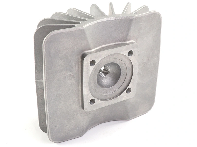
The chosen condition proceeds through the intended chemical preparation and coating trial. Adhesion and appearance are evaluated on the complete part. This scenario is not a Neway customer case and does not claim that the pictured casting is a heat sink or that it passed any specified value.
What to Include in a Sandblasting RFQ and Trial Approval
Provide 3D and 2D drawings, alloy and casting route, incoming surface, blasting objective, permitted or prohibited media, cosmetic zones, no-blast map, roughness requirement, edge and fin limits, downstream coating, cleaning, quantity, inspection and packaging. Ask the supplier to identify the proposed media class, fixture, coverage method, process evidence and change triggers.
RFQ Item | Buyer Input | Supplier Output |
|---|---|---|
Blast objective | Clean, texture, remove or prepare | Process and acceptance proposal |
Incoming condition | Oil, oxide, machining, repair and prior finish | Pre-clean and hold criteria |
Geometry risk | Fins, edges, cavities and fits | Support, angle, masking and inspection |
Surface output | Master, roughness and zone requirements | Measurable first-article evidence |
Downstream process | Coating, bonding or final bare finish | Cleaning and transfer controls |
Repeat production | Batch and annual volume | Media, nozzle, master and maintenance controls |
A release-ready blasting specification protects geometry while making the surface objective inspectable. It gives the supplier room to control validated equipment settings and gives the buyer evidence that texture, cleanliness and downstream performance remain stable across repeat orders.
FAQ
How Should Thin Cooling Fins Be Protected During Sandblasting?
Which Cast Defects Can Sandblasting Reveal Instead of Remove?
How Should Threads, Bores and Sealing Lands Be Masked for Blasting?
What Cleaning Evidence Is Needed After Sandblasting a Complex Housing?
How Should a Sandblasted Appearance Master Be Used for Repeat Orders?