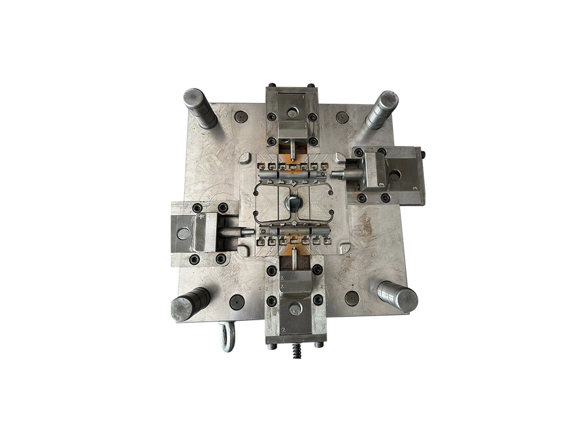
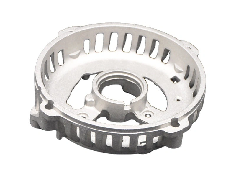
D2 Steel Composition for Die Casting Tooling: Wear, Heat Treatment and Maintenance
D2 steel composition is relevant to die-tool selection because its high carbon and high chromium alloy system is associated with wear resistance and dimensional stability after suitable heat treatment, but D2 is not a universal answer for every die-casting tool. Die casting exposes tool surfaces to thermal cycling, pressure, erosive metal flow, impact, machining, and repair. The correct choice depends on the alloy being cast, tool area, temperature history, geometry, production volume, maintenance plan, and whether toughness or wear resistance is the primary risk.
For a buyer, the important question is not only “what is D2 steel made of?” It is whether the specified D2 grade, condition, and heat treatment support the insert or tool feature being designed. D2 tool steel should be reviewed with cavity geometry, shutoffs, slides, gates, parting surfaces, machining, and repair. The RFQ should identify the standard, material traceability, heat-treatment record, and acceptance evidence rather than rely on a generic tool-steel label.
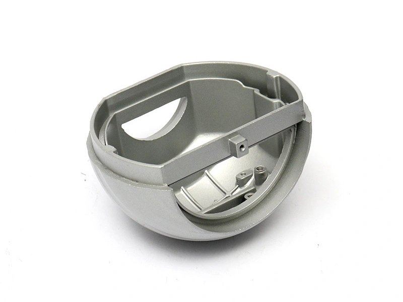
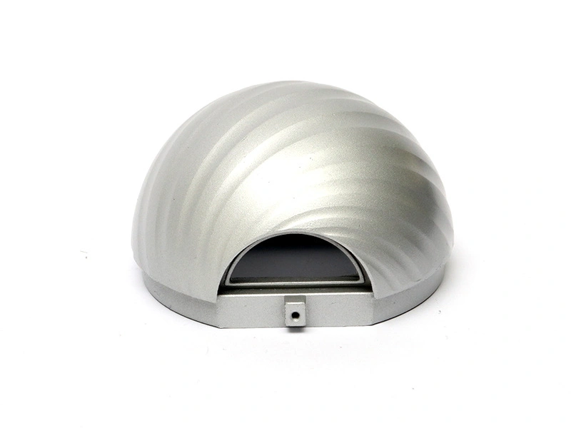
Read Composition as a Tool-Risk Clue
Carbon supports hardness potential and chromium contributes to wear and corrosion behavior in the alloy system, but composition does not determine the final tool condition by itself. Heat treatment, section size, machining sequence, surface finish, residual stress, and service temperature all influence the insert. A certificate can confirm a material chemistry range; it cannot prove that an insert will resist chipping or thermal fatigue in a particular die.
Higher hardness can help an abrasive surface, yet excessive hardness or poor toughness may increase chipping at a sharp shutoff, thin slide, or impact-prone edge. A tool area that sees repeated thermal shock may need a different balance from a gate or wear insert. The buyer should identify the tool feature and failure mode before selecting D2. The same steel may be suitable for one insert and unsuitable for another.
When the material is specified by a customer standard, keep the standard and condition visible in the tool drawing. If the supplier proposes another high-chromium tool steel, compare the required wear, toughness, heat-treatment, machining, and repair characteristics. “Equivalent D2” should be approved against the part of the tool that it will serve.
Tool area | Composition-related question | Evidence to request |
|---|---|---|
Gate or high-flow insert | Will erosion and thermal cycling dominate over impact? | Material certificate, heat-treatment record, and wear inspection plan |
Thin shutoff edge | Is edge retention balanced with chipping resistance? | Hardness/condition record and trial flash or edge review |
Large cavity insert | How will section size and residual stress affect stability? | Heat-treatment route, dimensional check, and tool trial |
Repairable insert | Can the selected condition be machined and repaired without changing fit? | Repair procedure, replacement datum, and post-repair inspection |
D2 Is Not Automatically the Best Die Material
Die tools face different loads depending on alloy, machine, gate velocity, cavity shape, cooling, and production cycle. A material that performs well under abrasive wear can still be vulnerable to thermal fatigue, impact, or a difficult repair. Other tool steels or localized inserts may be considered when the failure mode calls for a different balance. The choice should follow the tool area and service condition, not a blanket preference for a hard steel.
Tool material selection should be tied to the casting alloy and part geometry. A die for aluminum may experience a different thermal and erosion pattern from a die for zinc or a copper alloy. Slides, cores, gates, and shutoffs may each need a separate review. If the tool uses several materials, record where each is located and why.
Do not publish a fixed tool-life number for D2 without tool size, alloy, cycle, maintenance, heat treatment, and acceptance evidence. Tool life is a condition-based outcome. A cavity with a smooth flow path and robust inserts has a different risk from a tool with sharp edges, thin slides, deep pockets, and uneven cooling.
Heat Treatment Controls the Working Condition
Heat treatment changes hardness, toughness, dimensional stability, and residual stress. The supplier should state the intended condition and the records supplied. The route depends on the material standard, section, machining allowance, and tool function. Rough machining, stress relief, hardening, tempering, and finish machining may be sequenced to manage distortion, but the correct sequence must be confirmed by the toolmaker.
Large inserts and thin sections can respond differently during heat treatment. A cavity may need extra stock before hardening so that the final surface can be corrected. A slide or shutoff can move and require a controlled finish operation. Measure critical dimensions after heat treatment and after final machining, using the same tool datums that will be used for assembly.
Hardness is useful only when linked to the specified location and condition. A single reading on an accessible face may not represent a thin insert, a large cavity, or a repaired area. If hardness or metallurgical evidence is required, define the method, location, sample, and acceptance limit. Avoid quoting a generic value as proof of tool performance.
Machining and Surface Finish of D2 Inserts
D2 can require a carefully planned machining route because its hardened condition, carbide structure, section size, and final surface requirements affect tool wear and finishing. The die machining process may include milling, grinding, EDM, polishing, texturing, or a combination. The supplier should select the sequence around the cavity geometry and the required surface, not simply apply one operation to every area.
Sharp transitions, thin shutoffs, deep cavities, and small radii are difficult to finish consistently. A polishing operation can change an edge or enlarge a feature if the boundary is not controlled. A textured surface requires a reference and an inspection method. If the cavity creates a machined or cosmetic face on the part, approve the tool finish against the finished-part requirement.
Tool and part datums must stay connected. A cavity measured in a tool coordinate system may produce a part feature that is offset relative to the assembly datum if the tool is not set up correctly. Toolmaking should include a cavity-to-core and insert-to-base relationship check before tryout.
Thermal Cycling and Crack Risk
Die casting tools experience repeated heating and cooling. The thermal gradient depends on alloy, fill, cooling, section geometry, and cycle. D2's wear resistance does not remove thermal-fatigue risk. Corners, vents, gates, shutoffs, and areas near cooling passages can develop different stresses. Use suitable radii, avoid abrupt section changes in the tool, and review cooling layout with the insert design.
A crack or chip should be examined for location and mechanism. A crack at a sharp corner may suggest stress concentration or thermal fatigue. A chipped slide edge may point to impact, misalignment, or excessive hardness for that feature. A worn gate may reflect metal erosion, flow, or a surface condition. The repair should address the mechanism rather than merely restore the visual shape.
Inspection after a trial should record the tool area, casting symptom, cycle condition, and disposition. If a repair changes the shutoff, gate, vent, or cavity, recheck the associated part features. A successful repair is one that restores the tool relationship and the casting requirement, not only one that removes a visible mark.
Observed symptom | Possible tool question | Next evidence |
|---|---|---|
Repeated flash | Is the shutoff worn, misaligned, chipped, or thermally moving? | Shutoff inspection and parting-line measurement |
Gate erosion | Does the alloy flow and temperature exceed the insert's intended condition? | Gate inspection, process record, and insert material review |
Corner crack | Is the radius, cooling, hardness, or stress state appropriate? | Crack analysis, tool drawing review, and repair validation |
Dimensional drift | Is the cause wear, heat balance, setup, or cavity movement? | Tool measurement, warm-trial data, and part dimensional map |
Maintenance and Repairability
Maintenance should define what is inspected, how often it is checked, and which condition requires repair. Focus on gates, slides, shutoffs, ejector holes, cavity corners, cooling connections, and high-wear inserts. The correct frequency depends on the tool and production conditions. Do not promise a fixed interval without the alloy, cycle, and observed wear history.
Repairability is a design feature. Replaceable inserts can isolate damage; accessible shutoffs can simplify correction; a documented datum can make a replacement repeatable. A repair that requires hand fitting may be acceptable for a controlled tool, but the fit and final part should still be inspected. Store spare components with their material and heat-treatment records.
Tool ownership and maintenance responsibility should be written into the quote. Clarify who stores the tool, who approves material changes, who pays for repair, and which records accompany a repeat order. A high-wear material choice is only useful when the maintenance plan supports it.
RFQ Inputs for D2 Tool Steel
Provide the tool drawing or part model, alloy being cast, tool area, production volume, cycle assumptions, cavity and insert geometry, cooling, expected surface, repair strategy, material standard, heat-treatment requirement, inspection, and documentation. State whether D2 is mandatory or being compared with another tool steel. Explain the failure mode or requirement that drove the material discussion.
Ask the supplier to identify where D2 will be used, what condition is intended, how the material is verified, which surfaces are machined after heat treatment, and how the insert is maintained. Request a trial plan that checks flash, wear, dimensional stability, surface transfer, and the part features connected to the insert.
Neway's D2 steel route should be reviewed as a tool-material decision, not as a general guarantee of die life. The final approval depends on alloy, geometry, cycle, heat treatment, cooling, and inspection evidence.
Read D2 Composition Together With Tool Behavior
D2 steel composition is usually discussed through its high carbon and chromium content with additional alloying elements that influence hardenability, carbide structure, wear behavior, and dimensional response during heat treatment. The composition explains why D2 can be attractive for a wear-prone insert, but it does not establish the working condition of a finished tool. Heat treatment, section size, machining sequence, retained stress, surface finish, and the way the insert is supported all matter.
Carbide structure is a practical concern for a die tool. Wear resistance may improve in the right application, while coarse or poorly distributed carbides can affect toughness, grinding behavior, and the response to impact or thermal cycling. The buyer does not need a generic metallurgy lecture; the buyer needs the supplier to connect the selected D2 condition to the tool area. A small replaceable insert with a defined sliding wear problem is a different decision from a large cavity block with repeated thermal shocks and thin shutoffs.
Heat Treatment Is a Controlled State, Not a Material Footnote
Heat treatment changes hardness, dimensional stability, stress state, and the balance between wear and toughness. The required sequence should be defined by the material specification and tool design, then supported by a furnace or batch record and any agreed hardness or dimensional checks. The buyer should ask which surfaces are left for finish machining after heat treatment and how distortion is corrected without losing the approved geometry.
For deep pockets, thin shutoffs, and inserts with holes or slots, heat-treatment movement can affect assembly and parting. A toolmaker may leave stock, alter the insert boundary, or use a separate component so that the sensitive surface remains controllable. Those choices influence both price and repair. A D2 quote that lists only steel grade and nominal hardness leaves out the conditions that determine whether the tool can be measured and maintained.
Before release, inspect the D2 insert in the assembled tool and compare its working edge with the drawing. Check the interface, clearance, cooling access, and any finish allowance that remains after grinding. This catches a material-condition problem while the insert is still accessible, rather than after a casting defect is repeated across a production lot.
Choose D2 for the Dominant Risk
D2 may be reasonable where abrasive wear, sliding contact, or repeated edge damage is the leading concern. It may need closer review where the tool sees severe impact, rapid thermal cycling, or a geometry that concentrates stress. The alloy being cast, the thermal route, cooling layout, gate velocity, shutoff design, and maintenance frequency all affect that balance. If thermal fatigue or chipping is more likely than abrasion, a different tool material or a different insert geometry may be worth comparing.
The tool trial should be designed to reveal the dominant risk. Review flash at shutoffs, edge chipping, surface transfer, galling or sticking, dimensional movement, and the condition of slides and ejectors. Record the tool revision and casting conditions. If the first trial looks good but the production route changes temperature, cycle, alloy, or cooling, the evidence may no longer represent the working tool.
Plan Repair Around Replaceable Surfaces
D2 is often most useful when the design makes wear visible and repairable. Inserts can isolate a gate, corner, shutoff, or core print that is expected to need attention. However, an insert joint can introduce flash, mismatch, or a new thermal path. The buyer should ask how the insert is located, how it is removed, how its position is re-established after repair, and how the casting will be inspected after replacement.
Maintenance records should identify the affected tool area, measured condition, repair action, and post-repair verification. Hardness readings, dimensional checks, and visual observations are useful only when tied to a decision threshold agreed for that tool. Neway's tool material selection discussion can be used with the D2 scope, but the final choice remains dependent on alloy, geometry, process, and maintenance evidence.
What to Request for a D2 Tooling RFQ
List the D2 standard or supplier grade, tool location, starting condition, heat-treatment record, finish-machining plan, hardness or dimensional verification, trial features, maintenance scope, spare-insert requirement, and repair approval path. State whether D2 is mandatory or a proposal to solve a named wear problem. That gives the supplier room to make a useful comparison without allowing an unsupported material substitution.
Grinding and Surface Finish Can Change the Working Edge
D2's response to grinding, polishing, or another surface operation should be considered at the tool-feature level. A gate edge, shutoff, slide, or cavity corner may require different access and finishing from a broad support face. Poor access can leave a local step, overheat a surface, or make it difficult to restore the original geometry. The tool drawing should state which surfaces are functional, which are cosmetic, and which are allowed to be blended during maintenance.
If the tool is polished, the buyer should define texture, visible marks, and the inspection state. A polished face can still be out of position or create flash at a shutoff. Inspect the assembled tool and the casting. Neway's tool and die making route can be reviewed with the D2 specification and repair plan.
Requalify When Tool Exposure Changes
A new casting alloy, cycle, die temperature, cooling arrangement, or surface treatment changes the exposure of a D2 tool. Record the change and review wear, thermal fatigue, sticking, flash, and dimensional effects. The original tool-material selection may remain appropriate, but that conclusion should be supported by the changed process and sample evidence.
Buyer Summary
D2 steel composition helps explain wear and hardness potential, but the working behavior of a die insert also depends on heat treatment, toughness, thermal cycling, geometry, machining, and maintenance. D2 may suit a defined wear risk and may be inappropriate where impact or thermal fatigue dominates.
Specify the tool area, material standard, condition, heat-treatment record, trial evidence, and repair path. That lets a buyer judge D2 on the performance the insert must deliver rather than on a material name alone.
FAQ