Sandblasting Surface Roughness for Cast Parts: How Buyers Specify Texture and Inspection
Sandblasting surface roughness for cast parts should be specified as a measurable surface condition linked to location and function, not as a universal Ra value or the phrase “uniform matte.” Buyers need to separate three outputs: numerical profile, visual texture and downstream performance. Those outputs overlap, but none can replace the others.
Ra and Rz can help control process drift when the measurement method is repeatable. They cannot fully describe particle-scale shape, directional lay, gloss, color variation or an isolated gouge. A physical appearance master can control texture and reflectivity, but it cannot prove a coating has adequate adhesion or that a sealing land retained its functional finish. The drawing and quality plan therefore need a combined acceptance system.
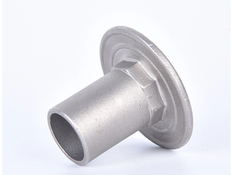
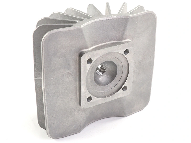
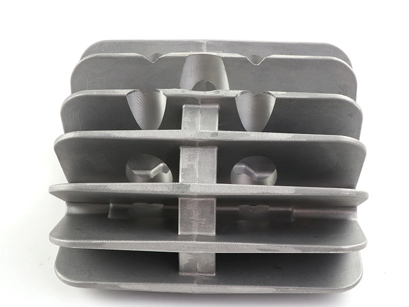
No roughness number can be read from a photograph. The two images in this article only provide geometry context for discussing broad faces, curved walls, holes and edge zones. Production acceptance requires actual instruments, defined settings and traceable samples.
What Is the Difference Between Blasted Texture and Surface Roughness?
Surface roughness is a measured representation of short-wavelength height variation after an instrument and filter separate it from waviness and form. Blasted texture is the broader visual and tactile result produced by cast skin, abrasive impacts, local coverage, color and reflectivity. Two parts can have comparable roughness readings yet look different under directional light because peak shape, lay and gloss are different.
The distinction matters when a buyer uses one surface as a visible final finish and another as preparation for powder coating. The final bare surface may require an approved appearance master and controlled viewing. The coating-preparation surface may require a profile window, cleanliness evidence and a complete adhesion trial. A number that works as a process monitor for one objective may be irrelevant or incomplete for the other.
Surface Requirement | Primary Evidence | What It Cannot Prove Alone |
|---|---|---|
Average roughness | Ra using defined instrument, filter and location | Peak severity, gloss or visual uniformity |
Peak-to-valley behavior | Rz or other specified profile parameter | Complete visual texture or coating adhesion |
Cosmetic appearance | Approved master, zones, light and viewing distance | Hidden cleanliness or functional profile |
Coating readiness | Profile, cleanliness and complete coating tests | Final bare-metal appearance |
Functional interface | Drawing finish, geometry and functional verification | Acceptability of surrounding cosmetic areas |
Specifications should identify whether each surface is A-class cosmetic, secondary visible, hidden, coated, bonded, sealed or machined. The supplier can then use the correct evidence instead of averaging unrelated surfaces into one result.
How Ra, Rz and Profile Shape Answer Different Questions
Ra is the arithmetic average of absolute profile deviations within the evaluation length. It is useful for monitoring average texture but can hide isolated high peaks and deep valleys. Rz emphasizes peak-to-valley characteristics through its defined calculation and can respond more strongly to aggressive particles, gouges or mixed media. The exact Rz definition can vary by standard edition and instrument, so the drawing should state the applicable method instead of assuming all reported Rz values are interchangeable.
Neither parameter captures surface direction by itself. Blasting should generally create a stochastic impact texture, yet operator sweep, nozzle angle or fixture shadow can create visible lay. A stylus traced parallel to a directional pattern may report differently from a perpendicular trace. Specify measurement direction or multiple directions when lay is relevant. For isotropic optical measurements, state the areal parameter and processing method rather than substituting it silently for a profile result.
Parameter or Observation | Useful For | Specification Detail Needed |
|---|---|---|
Ra | Average process texture trend | Standard, filter, cutoff, evaluation length and direction |
Rz | Peak/valley sensitivity | Definition, instrument setup and sampling position |
Profile trace | Gouges, mixed texture and process comparison | Raw trace retention and interpretation rule |
Lay | Directional marks or operator sweep | Viewing and trace direction |
Gloss/reflectivity | Visual consistency | Instrument geometry or master viewing condition |
Do not copy a roughness range from another casting unless alloy, cast surface, abrasive route, geometry, function and measurement method are comparable. The appropriate range should come from qualification samples that satisfy the actual cosmetic or downstream requirement.
Where and How Should Roughness Be Measured on a Casting?
Measurement locations should be marked on the drawing or a controlled surface map. Broad flats are easiest to measure but may not represent curved walls, fin roots, recesses or zones near holes. A stylus needs enough straight travel and stable seating. Curvature can add form to the trace, and an instrument may filter that form differently from another. Optical methods can reach some areas without contact but require their own calibration, focus, reflectivity and filtering controls.
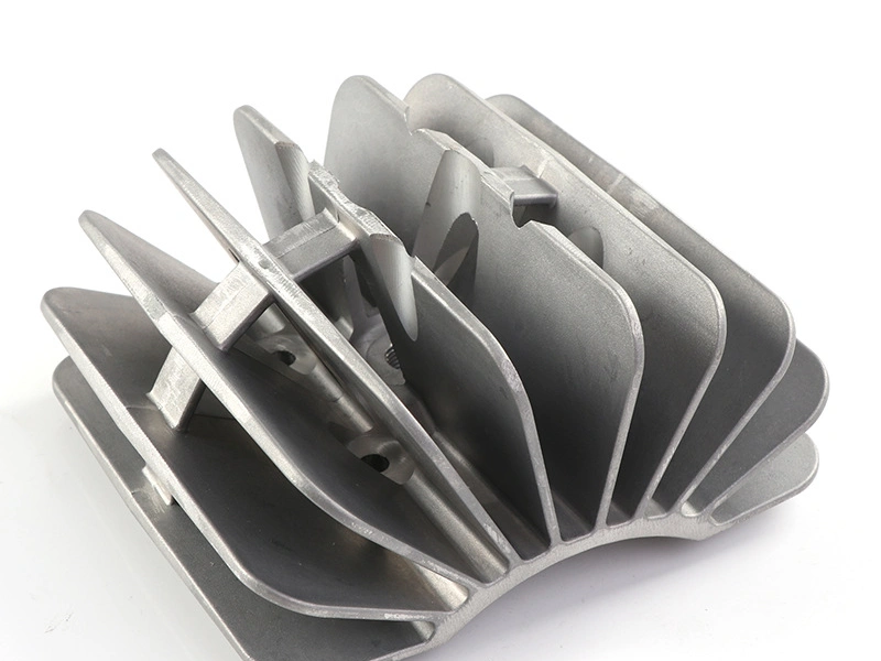
Keep routine traces far enough from edges, holes, parting lines, ejector marks and local repairs unless those features are intentionally being evaluated. Near an edge, the stylus can lose support or measure a transition rather than the blasted surface. On a cylinder, define angular location and axial or circumferential direction. On fins, distinguish tip, side and root because their blast exposure differs.
Location Type | Measurement Risk | Control |
|---|---|---|
Broad cast flat | Easy location may not represent worst geometry | Use as one process-control zone, not the whole part |
Curved wall | Form and stylus seating influence trace | Define radius range, direction and compensation method |
Hole edge | Transition, rounding and measurement dropout | Specify exclusion distance and separate edge inspection |
Fin root | Instrument access and blast shadow | Use approved optical/replica method or visual zone |
Machined island | Different starting texture from cast skin | Separate acceptance and trace identity |
Parting line area | Trim and flash-removal variation | Do not treat as normal field unless specifically required |
The measurement system should be studied on actual part geometry. Repeatability across operators, fixtures and instruments matters before the value is used for acceptance. When no instrument can reach the functional area, a correlated witness, replica or optical method may be possible, but the correlation must be demonstrated rather than assumed.
How Blasting Variables Create Roughness and Texture Drift
Abrasive material, particle shape, size distribution, hardness, density and breakdown influence the impact pattern. Equipment pressure or wheel speed, nozzle wear, standoff, angle, dwell, sweep overlap, rack loading and part orientation influence delivered energy and coverage. Cast skin, oxide, prior machining and local hardness influence how the surface responds. The measured profile is therefore an output of the complete system, not a property of the media name alone.
Media changes during use. Rounded beads can fracture and create fines; angular particles can break into smaller sharp fragments. Replenishment changes the fresh-to-used ratio. Dust separation removes selected sizes, and contamination from prior jobs can introduce a second texture. Useful context on specialty media blasting and non-metallic blasting media supports media review, but production limits still require a part-specific trial.
Drift Source | Possible Surface Signal | Monitoring Direction |
|---|---|---|
Media breakdown | Finer texture, dust or changing Rz | Sieve/condition check and roughness trend |
Nozzle wear | Wider pattern and lower/local energy shift | Nozzle identity, diameter and coverage result |
Standoff or angle | Different impact shape and directional appearance | Fixture, path and first-piece map |
Long dwell | Higher profile, rounded edges or exposed pores | Cycle/path control and geometry inspection |
Cross contamination | Mixed marks, staining or embedded particles | Cabinet segregation and residue analysis |
A control chart can trend values from fixed part locations, but a stable average does not release visible streaks or local overblast. Pair numerical trends with the approved visual and geometry checks. Reaction rules should identify containment, media/equipment investigation, remeasurement and authority to resume.
How an Appearance Master Complements Roughness Numbers
An appearance master captures texture scale, reflectivity, acceptable local variation and the interaction between blasted surface and cast geometry. It should represent the delivered condition, including any clear protection or later painting when that treatment changes appearance. A freshly blasted bare sample is not a valid final master for a part delivered after coating.
Define A, B and C zones, viewing distance, light direction, illuminance or approved booth, viewing time and prohibited defects. Retain upper and lower boundary samples when a single “golden sample” invites subjective interpretation. Mark the non-viewing side with part revision, process route, approval date and responsible parties without contaminating the evaluated surface.
Store masters in clean, dry, protected packaging. Bare aluminum can oxidize, stain or collect fingerprints, changing comparison. Inspect the master at planned intervals and after any suspected damage. When replacement is necessary, compare old, proposed and recent production samples under the same conditions, record the reason and obtain approval before the old sample is retired.
Decorative coating controls provide additional context for master-sample handling when the blasted texture remains visible through the delivered finish.
How Powder and Paint Change the Meaning of the Blasted Profile
Powder and wet paint can cover fine texture, bridge valleys, emphasize larger defects or produce different gloss over profile extremes. The substrate profile can influence mechanical keying and coating distribution, but rougher is not always better. High peaks may receive reduced film at their tips, while deep valleys can retain abrasive, cleaner or conversion chemistry. The approved coating supplier must define the acceptable prepared surface for the selected system.
For a coated part, release the substrate and finished film separately. Record profile before coating at specified locations, then inspect dry-film thickness, cure, adhesion, appearance and service-specific performance after coating. A final coating thickness reading cannot reconstruct the original profile. Likewise, a passing roughness value does not prove the surface was free of oil or loose media.
Blasted-Surface Output | Coating Interaction | Release Evidence |
|---|---|---|
Fine uniform profile | May be visually covered by film | Cleanliness plus full coating qualification |
Sharp high peaks | Can create local low film at tips | Profile limit and DFT/edge inspection |
Deep valleys | Can retain residue or chemistry | Cleaning, rinse and dry validation |
Directional blast marks | May remain visible under thin/gloss film | Finished appearance master |
Opened pore | Can contribute to pinhole/outgassing risk | Casting disposition and controlled coating trial |
How to Build First-Article and Production Sampling
First article should map all surface classes and the locations most likely to receive high, low or changing blast exposure. Record the exact instrument configuration and raw readings, visual-master result, media condition, equipment, orientation and date. Include measurements after fresh media addition and at normal aged condition when media life can shift the process.
Routine production can use fewer fixed locations only after correlation shows they predict the wider map. Sampling frequency should increase after new media, major replenishment, cabinet cleanout, nozzle replacement, fixture change, maintenance, part revision or a texture nonconformance. A failed location should trigger containment back to the last accepted check and evaluation of all affected zones, not only remeasurement on a convenient flat.
Stage | Minimum Decision Evidence | Purpose |
|---|---|---|
Media/process screening | Representative coupons plus actual cast surface | Eliminate unsuitable profile directions |
First article | Full location map, visual zones and geometry | Establish approved surface condition |
Pilot batch | Part-to-part and media-age variation | Confirm production stability |
Routine production | Fixed trend points plus visual release | Detect drift efficiently |
Change/restart | Expanded map and master comparison | Verify changed conditions remain qualified |
Hypothetical Measurement Map for a Circular Cast Housing
Consider a hypothetical circular aluminum housing with a broad outer face, cylindrical wall, bolt holes, an internal rim and one machined interface. The outer face is A-class cosmetic and receives three traces at defined angular positions. The cylindrical wall receives axial and circumferential traces at one controlled radius. Hole edges are evaluated visually and by edge geometry because the stylus cannot produce a stable trace close to the transition.
The internal rim is a coating-preparation zone and uses a separately qualified optical or replica method if direct stylus access is impossible. The machined interface is masked and retains its drawing finish; it is not averaged with blasted locations. All points are identified on a controlled map, and the appearance master covers the complete A surface under fixed lighting.
This example shows how one component can need several acceptance methods. It does not establish universal locations or values, and it does not claim the pictured component received these measurements.
What to Include in a Sandblasted Roughness RFQ
Provide the casting process and alloy where known, drawing revision, incoming surface condition, blast objective, surface-zone map, numerical roughness requirement with full measurement method, cosmetic master requirement, no-blast features, downstream coating, quantity and inspection records. Ask the supplier to identify media control, equipment route, measurement access and production reaction plan.
The broader post-process plan should keep roughness evidence connected to later machining, coating and assembly requirements. If the cast surface itself changes through a tooling or process revision, the aluminum die casting and blasting teams should review the approved baseline together.
RFQ Item | Buyer Must Define | Supplier Must Return |
|---|---|---|
Surface function | Cosmetic, coated, bonded, sealed or hidden | Proposed route for each zone |
Roughness | Parameter, limit, method and location | Measurement capability and sample data |
Appearance | Master, viewing and defect limits | Boundary-sample and storage plan |
Protected geometry | Threads, bores, seals and datum surfaces | Mask and edge inspection method |
Production control | Required records and notification | Media-age, sampling and reaction controls |
Downstream finish | Powder, paint, bond or bare delivery | Complete validation evidence |
A useful blasted-surface specification does not chase one number. It defines what the surface must do, how and where it is measured, what it must look like, and how the supplier proves that the condition remains stable as media and equipment age.
How Drawing Notation and Measurement Uncertainty Prevent Disputes
A roughness symbol without a process stage or measurement detail can create conflicting interpretations. The buyer may intend a post-blast value on cast skin, while the supplier measures a machined witness before blasting or reports the instrument default. State whether the requirement applies before or after coating, whether material removal is allowed, and which surfaces or zones are excluded. Reference the applicable standard edition because parameter definitions and filtering conventions can change.
Inspection agreement should also address resolution and measurement uncertainty. A narrow acceptance band is unusable when part placement, curvature, instrument repeatability and surface nonuniformity consume most of that band. During method approval, repeat traces by multiple operators, remove and replace the part in its fixture, and compare instruments if both buyer and supplier will inspect. The goal is not to manipulate borderline values; it is to ensure that a reported difference reflects the surface rather than the method.
Agreement Item | Required Decision | Dispute Prevented |
|---|---|---|
Process stage | As-cast, post-blast, post-clean or final coated | Comparing different surface conditions |
Standard edition | Named parameter and current agreed reference | Different Rz or filter interpretations |
Instrument program | Tip, cutoff, filter, length and direction | Default-setting variation |
Location tolerance | Coordinate patch and edge exclusions | Choosing favorable points |
Borderline result | Repeat method and disposition authority | Repeated measurement until one value passes |
Capability analysis should use individual mapped readings as well as averages. Averaging three zones can hide one consistently overblasted edge. Preserve raw results for first article and significant changes so a later investigation can distinguish a true process shift from an inspection-system change.
FAQ
Why Can Two Sandblasted Parts Have Similar Ra but Different Appearance?
Where Should Roughness Be Measured on Curved or Finned Cast Surfaces?
How Does Blasting-Media Wear Change Surface Texture Across a Batch?
Should a Coating-Preparation Profile Be Inspected Differently From a Final Cosmetic Finish?
How Should Buyers Preserve and Replace a Sandblasted Master Sample?