Aluminum Die Cast Parts: How Buyers Specify Geometry, Machining, Finish, and Production Scope
Aluminum die cast parts work best when the buyer specifies the finished component rather than asking for an attractive casting at the lowest blank price. The drawing and quotation package should connect geometry, alloy, die-casting route, machining state, surface treatment, inspection, packaging, and order pattern. A housing with bores, ribs, bosses, and a sealing flange may be a good die-casting candidate when the design is stable enough to justify a die and the integrated shape removes downstream assembly or machining work. It is a poor candidate when the required faces, material condition, or validation state remain undefined.
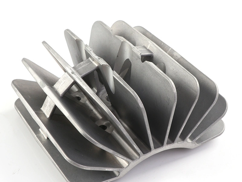
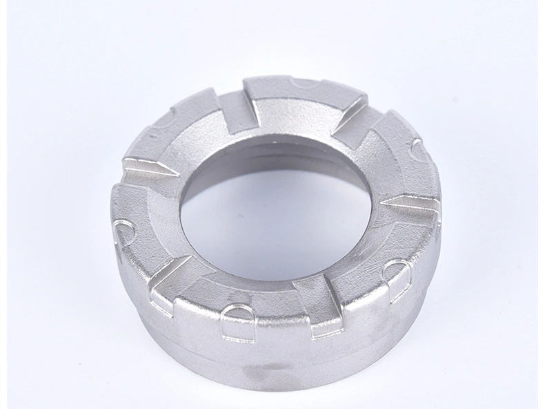
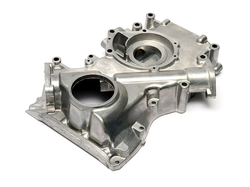
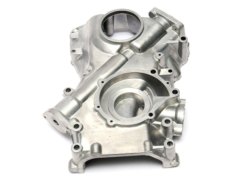
The two housings shown here illustrate the kind of geometry that needs a joined design and manufacturing review: circular openings, local bosses, thin walls, internal supports, and broad faces that may become datums or cosmetic surfaces. The images are visual references only. They do not prove a particular alloy, customer application, pressure result, dimensional capability, or production history. Those claims require a drawing, material definition, process record, and part-specific inspection.
When Are Aluminum Die Cast Parts a Sensible Route?
Choose aluminum die casting when one repeatable tool can form a meaningful portion of the part envelope and when the order pattern can support the tool investment. The strongest candidates often combine a shaped housing, ribs or bosses, openings, and several related faces that would be expensive to machine from a solid block. Die casting can also reduce the number of separate pieces when the integrated geometry is compatible with filling, ejection, trimming, and final operations.
That decision is not based on weight alone. A buyer should compare the complete delivered route with alternatives. The comparison includes die design, inserts or slides, trial work, material, trimming, CNC operations, deburring, coating, inspection, packaging, maintenance, and the commercial effect of the expected order pattern. The aluminum die casting service route is worth considering when the drawing has enough stability for those decisions to be made together.
Full CNC machining may still be better for a one-off part, a rapidly changing design, or geometry that has no useful repeatable casting envelope. Sand, gravity, or low-pressure casting may be better when the part size, alloy condition, section design, or quantity does not fit high-pressure die casting. The right question is not “Can this shape be cast?” It is “Which process produces the required finished part with an acceptable combination of tooling, material, machining, surface, inspection, and change risk?”
Start the Specification With Functional Geometry
Begin with the functions that the aluminum die cast part must perform. Mark locating bores, bearing seats, gasket lands, threaded holes, mounting pads, connector openings, thermal-contact faces, electrical contact areas, and any surface that carries a load or establishes position. Separate these features from ribs, cosmetic transitions, nonfunctional reliefs, and surfaces whose as-cast condition is acceptable. This map tells the die designer where filling and ejection freedom exists and tells the machinist which faces need a controlled setup.
Use one controlled 3D model and one controlling drawing or model-based definition. Identify the revision, units, datum scheme, material callout, surface notes, and precedence when documents disagree. Show mating parts when a clearance, seal, bearing, connector, or fastener determines the envelope. A casting supplier can make a better DFM recommendation when the functional relationship is visible instead of being inferred from isolated dimensions.
Geometry that looks simple in a rendered model can create a difficult casting sequence. A boss joined to a broad wall can cool differently from a thin rib. A deep pocket can restrict die access, trap air, or complicate ejection. A long opening can be affected by a slide, core, or parting line. A flange can be easy to form but difficult to keep stable during machining if the casting is flexible. These are design questions before they become production defects.
Geometry Element | Question Before Tooling | Decision It Supports | Evidence After Trial |
|---|---|---|---|
Locating bore | What feature controls its position and will it be machined? | Datum sequence, core strategy, machining stock, and inspection state | Diameter, position, alignment, and assembly check in the defined condition |
Sealing flange | Does the final boundary require a milled face and a leak test? | Stock map, support strategy, masking, and test fixture | Flatness, surface condition, and specified finished-part test |
Rib field | Can ribs fill, eject, and clear the mating part without unnecessary machining? | Draft, transition, parting, and acceptable as-cast condition | Profile, flash, clearance, and functional or visual inspection |
Threaded boss | Is the thread cast, drilled, tapped, or formed by another operation? | Wall around the hole, core pilot, stock, and deburring scope | Thread gauge, depth, position, and torque requirement when specified |
A useful DFM response does more than list draft and parting-line comments. It should show which proposed changes protect a functional interface and which changes are only manufacturing preferences. For example, moving a gate away from a sealing face may be important, while moving a nonfunctional rib transition may be negotiable. The buyer should record that distinction before tool release so a later optimization is not mistaken for a product change.
Choose the Aluminum Alloy With the Process
Aluminum die cast parts should be specified with an alloy and a process route together. A380 and ADC12 are often evaluated in high-pressure die-casting programs because the route can form detailed repeat geometry, but the offered grade, governing specification, melt practice, and delivered condition still need to be named. A356 belongs to a different decision path when gravity, low-pressure, or sand casting and a specified material condition are under consideration. An alloy name alone is not a substitute for the actual process and acceptance basis.
Screen the alloy against the finished part. Ask how the selected grade relates to corrosion exposure, pressure or leak requirements, machining, thermal duty, surface treatment, ductility needs, local section changes, and the required material record. If the part contains a sealing flange or a drilled passage, internal discontinuity risk may matter more than a generic strength comparison. If the part has a visible exterior, finish response and surface preparation may carry more weight than an isolated data-sheet value.
The A380 material reference and the A356 casting reference can help organize grade-specific questions. They should be read as starting points, not as approval of a substitute for a particular drawing. When a supplier proposes an alternate grade, require the change to identify the standard, composition basis, delivery condition, casting route, machining effect, finish effect, and new evidence required for release.
Review Filling, Venting, and Ejection Before Freezing the Die
Filling and ejection decisions shape the quality of aluminum die cast parts before any CNC operation begins. The supplier should review gates, overflows, vents, slides, cores, cooling assumptions, and likely ejector locations against the functional map. A part can have a clean outside appearance while a local boss, thick transition, or enclosed pocket retains gas or develops a discontinuity. A later machining cut may expose that condition.
Use mold-flow analysis to compare decisions, not to create a decorative simulation report. The review should state which gate or overflow arrangement was considered, where air evacuation is expected, which regions are difficult to fill, and what design or process change follows. The mold-flow analysis guidance is useful for framing that discussion. The simulation remains dependent on the alloy, die design, thermal state, process settings, and assumptions used.
Ejection deserves the same attention. A deep pocket, tall boss, or uneven wall can require a force path that affects the casting or leaves a mark in an unacceptable zone. Parting lines and ejector witnesses should be mapped to visible and functional surfaces. The buyer can allow more freedom on hidden nonfunctional faces while protecting sealing lands, locating features, connector interfaces, and appearance zones.
Separate As-Cast, Trimmed, and Machined States
Every important dimension should have a stated part condition. “As-cast” means the feature is accepted in the casting state; “trimmed” adds removal of gates and flash; “machined” adds a defined CNC setup and material removal; “finished” may add coating or another surface operation. Confusing these states is a common reason a quote, sample, and inspection report appear to disagree.
Keep the casting for geometry that does not need close location, flatness, roundness, thread quality, or controlled surface texture. Ribs, nonfunctional reliefs, outer envelopes, and suitable bosses often remain as-cast after trimming. Plan CNC machining for interfaces where a mating component, seal, bearing, connector, or load path controls the requirement. The decision depends on the drawing, material, wall support, expected casting variation, and evidence method rather than on the nominal feature label.
Machining stock must be visible in the DFM response. Too little stock can leave an incomplete face; too much can expose a subsurface discontinuity, weaken a wall, or add unnecessary cycle and tool wear. A fixture also needs a stable datum. If it locates on flash, a flexible wall, or an unqualified ejector area, the part may be forced into position during cutting and relax after unclamping.
The CNC machining route should therefore be quoted with setup datums, supports, stock, tool access, deburring, chip removal, and the final inspection state. The relevant output is not a promise that every surface will be machined. It is a feature map showing which operation creates each functional interface and how that interface will be measured.
Part State | Suitable Questions | Typical Buyer Control |
|---|---|---|
As-cast | Is the profile, wall, rib, or boss adequate without cutting? | Drawing zone, flash rule, profile check, and functional clearance |
Trimmed | Are gates, runners, and flash removed without changing the datum? | Trim boundary, witness rule, edge condition, and visual review |
Machined | Which datum and stock create the bore, face, hole, or thread? | Setup plan, program revision, dimensional report, and assembly check |
Finished | Does coating or another process alter fit, appearance, or corrosion protection? | Mask map, surface definition, process record, and final-state inspection |
Control Porosity and Distortion by Risk Zone
Do not apply one generic defect rule to every aluminum die cast part. Mark the zones where a defect could change function: sealing flanges, drilled ports, threaded bosses, bearing bores, thin load paths, and connector areas. Gas porosity, shrinkage-related voids, oxide-related discontinuities, cold shuts, flash, and distortion have different mechanisms and different consequences. The same indication may be acceptable in a hidden nonfunctional rib and unacceptable in a pressure boundary after machining.
Connect the risk map to the process. Heavy transitions and isolated bosses should be reviewed with filling, cooling, venting, and machining stock. A flange near a gate needs a trim and flatness review. A long thin wall needs a fill and distortion review. A drilled passage needs internal integrity and final-state test logic. This is more informative than asking for a vague “defect-free” casting.
Choose inspection evidence for the question being asked. Visual inspection can identify surface condition and flash; dimensional measurement can identify position and warpage; sectioning or imaging can examine a defined internal region; and a leak test can evaluate a finished boundary under specified conditions. No single method proves every internal and functional requirement. If pressure retention matters, define the finished machining state, test medium, pressure or vacuum, stabilization, duration, allowable result, fixture, and sample plan.
Distortion can also be hidden by machining. A fixture may make a flange appear flat while the free part is bowed, or it may transfer a casting error into another datum. Compare fixture-state and free-state results where the assembly depends on the unclamped shape. The testing equipment overview can support a method discussion, but the buyer still needs a part-specific inspection plan with zones, datums, limits, and reaction rules.
Define Surface Finish and Corrosion Protection as a System
Surface treatment is part of the aluminum die cast part, not an afterthought applied to a generic blank. The substrate, casting surface, cleaning method, masking, coating, curing, and final inspection all interact. A coating that protects an exterior may cause trouble on a gasket land, electrical contact, threaded hole, bearing seat, or press-fit surface. The drawing should identify which faces receive the treatment and which remain protected, machined, or bare.
Separate appearance from performance. A visible housing may need an appearance reference, controlled texture, edge treatment, and a consistent view condition. A hidden bracket may prioritize corrosion protection and assembly clearance. A thermal or grounding face may require a controlled contact surface. “Black finish” or “surface treated” does not define preparation, coverage, thickness, mask boundary, adhesion, or acceptance.
Review the route with the post-process supplier before the die and machining plan are fixed. The post-process service scope can be used to discuss cleaning, deburring, blasting, conversion, coating, curing, masking, and inspection. If coating buildup can change a thread, slot, seal, or fit, decide whether the feature is protected, machined before treatment, or inspected only in the final delivered state.
Make Volume and Delivered Scope Visible in the Quote
Tooling economics depend on more than an annual number. Separate prototype or trial demand, launch quantity, normal order lot, forecast, peak requirement, design stability, and expected program duration. These inputs influence whether the die is justified, how much process development is sensible, how sampling is planned, and how packaging or inventory is managed. If quantities are uncertain, label them as planning assumptions rather than presenting them as firm demand.
Price the delivered component. State whether the quotation includes die design, tool build, trial shots, trimming, CNC machining, deburring, cleaning, surface treatment, leak or functional testing, dimensional reports, marking, packaging, tooling maintenance, and change work. A lower casting-blank price is not necessarily lower cost when it leaves the buyer to manage machining, finishing, inspection, and rejected interfaces separately.
For a useful comparison, ask each bidder to identify included operations, exclusions, assumptions, non-recurring tooling, recurring piece price, sample stages, and the commercial effect of a drawing revision. That keeps purchasing from comparing a raw casting with a finished and inspected part. It also gives engineering a place to review whether a proposed process can create the geometry the quote assumes.
Commercial Input | Why It Changes the Part Plan | What the Buyer Should Clarify |
|---|---|---|
Geometry revision | Changes parting, slides, stock, fixtures, and inspection | Controlling model, drawing revision, units, and change authority |
Order pattern | Changes tool economics, sampling, capacity, and packaging | Trial, launch, lot, forecast, peak, and program assumptions |
Finished operations | Changes cycle, labor, fixtures, process risk, and price | Trim, CNC, deburr, clean, coat, test, inspect, and pack scope |
Acceptance basis | Changes reports, gauges, test fixtures, and reaction work | Part state, CTQs, method, limit, sample plan, and approval owner |
What Should Buyers Send for an Aluminum Die Cast Parts Review?
Send the latest 3D model and 2D drawing or model-based definition, along with mating interfaces and any product notes that affect casting. Mark datums, sealing faces, bores, threads, mounting pads, visible zones, contact areas, thermal lands, and features that cannot move. Identify the required material or the constraints that keep the grade open. State the desired delivered condition, including machining, finish, testing, inspection, marking, and packaging where applicable.
Also send the order pattern in a way a supplier can price honestly. Distinguish one-time trials from normal orders and separate a forecast from a firm commitment. If the design may change, say which features are stable and which are still under development. This lets the supplier keep negotiable manufacturing details open while protecting the interfaces that cannot move.
Ask for a response that returns decisions in the same structure: proposed process, alloy basis, DFM changes, die assumptions, machining feature map, surface route, inspection plan, included operations, exclusions, and unresolved questions. The purpose is not to force every supplier into identical wording. It is to make differences visible before a tool or production promise is approved.
Use a Finished-Part Example to Test the Specification
Consider a generic aluminum enclosure with two circular openings, several mounting bosses, internal supports, and a broad perimeter flange. The buyer wants the casting to provide the outer envelope and ribs, while CNC machining creates the locating openings and a controlled gasket face. The image pair supports discussion of these geometric relationships, but it is not evidence of a customer program or a specific application.
The design review first marks the flange, openings, bosses, and rib field. The flange receives a machining-stock and free-state distortion review. The openings are assigned a datum relationship and a final machining operation. Bosses are checked for core access, wall support, drilling, threads, and the possibility that machining will expose an internal discontinuity. Ribs remain as-cast if their profile and clearance are adequate.
The process review then connects gate, overflow, vent, ejection, trimming, fixture, and inspection decisions. A trial sample is not approved merely because it looks good. The buyer asks which features were measured in the final state, whether the fixture represents production support, and whether any hand fitting or selective polishing was used. If the enclosure is a pressure boundary, the leak test is defined after the specified machining and finish operations.
This example shows why a useful aluminum die cast parts specification is a chain rather than a list. Geometry determines process choices; process choices affect stock and defect exposure; stock and datums affect machining; machining affects final fit and leak paths; surface treatment affects dimensions and corrosion behavior; and the delivered scope determines what purchasing is actually comparing.
Release Aluminum Die Cast Parts by Evidence, Not by Appearance
Release the route when the drawing, alloy, die, machining, finish, inspection, and commercial scope describe the same finished component. Keep an item open when a functional interface has no defined state, when a substitute material has no approval basis, when a test does not represent the delivered part, or when the quote excludes operations needed for assembly. A photograph can confirm that a shape exists. It cannot prove the material, datum relationship, free-state condition, coating fit, or internal quality of a production part.
For a new project, the practical next step is to send the controlled model, drawing, functional feature map, alloy constraints, quantity pattern, finished operations, and acceptance questions together. Ask the supplier to identify assumptions before tooling. This creates a clear boundary for aluminum die cast parts: a process choice made for a defined component, under defined conditions, with evidence that answers the risks that matter to the buyer.
FAQ
What Design Details Matter Most When Ordering Aluminum Die Cast Parts?
Which Aluminum Die Cast Parts Need CNC Machining After Casting?
How Should Buyers Control Porosity and Warpage in Aluminum Die Cast Parts?
How Should Buyers Choose A380, ADC12, or A356 for Aluminum Die Cast Parts?
What Production and Surface Records Should Buyers Require for Aluminum Die Cast Parts?