What Is Die Cast Tooling and Why Is It Important?
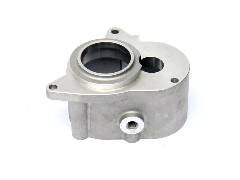
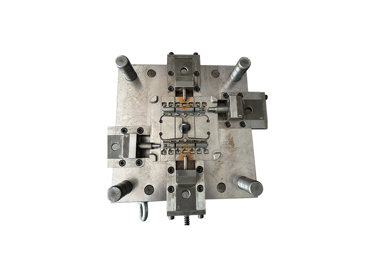
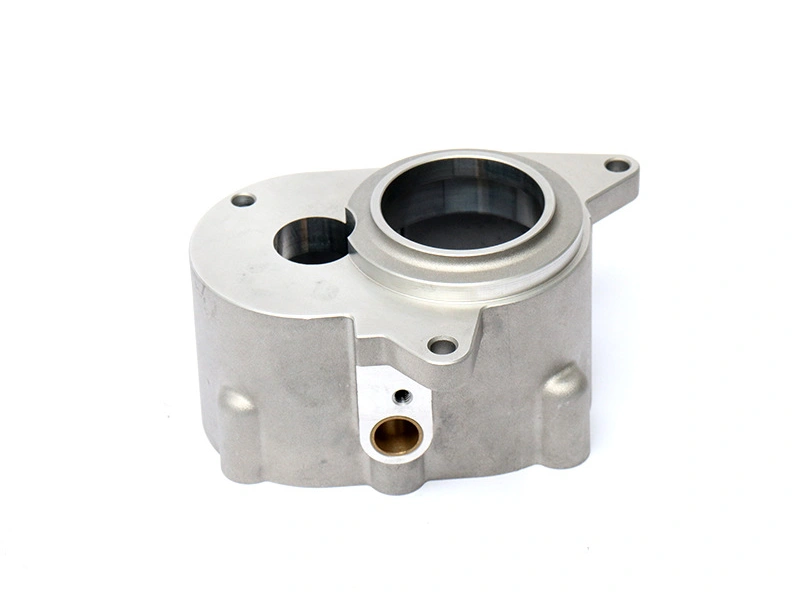
Die cast tooling is the complete, machine-mounted system that shapes molten alloy and controls filling, gas evacuation, heat removal, part release and repeat production. It includes cavity and core components, die blocks, gates, runners, overflows, vents or vacuum connections, thermal circuits, ejectors, slides, inserts, alignment and support hardware, trim interfaces and any specified sensors. It is important because these connected elements determine whether the released part can be made repeatedly, not merely whether one cavity resembles the CAD model.
The tool is a system, not only a cavity
The cavity and core establish the casting envelope, parting line, draft, ribs, bosses and other formed features. They do not work independently. Molten metal must reach those features through a suitable runner and gate; displaced air needs a route through overflows and vents; each region must reach a repeatable thermal condition; and the casting must leave the die without drag or distortion. A slider adds another opening direction, but also creates shutoffs, wear surfaces and sequencing requirements.
The die must also fit the production cell. Platen and tie-bar clearances, shot position, clamping requirements, water and vacuum connections, extraction, spray access and trim handling all influence usability. A technically correct insert that conflicts with a machine interface can stop production. This is why tool and die making should be reviewed with the intended machine and downstream route.
Tool subsystem | What it controls | Evidence buyers should request |
|---|---|---|
Cavity, core and shutoffs | Geometry, parting-line condition, formed stock and release surfaces | Approved split, draw directions, insert boundaries and dimensional inspection plan |
Runner, gates and overflows | Fill sequence, local metal velocity, flow-front destination and trim vestige | Layout review plus trial results correlated to cavity and process data |
Vents or vacuum | Escape of cavity air and gases during filling | Evacuation paths, connection details and cleaning access |
Thermal circuits | Die temperature distribution, solidification and dimensional stabilization | Circuit schematic, leak test and trial temperature observations |
Ejectors and slides | Release, side features, movement sequence and witness locations | Bench function check and trial evidence for drag, marks and alignment |
Machine and trim interfaces | Mounting, utilities, extraction and removal of runner or flash | Cell compatibility review and representative trimmed samples |
Tool interfaces create part quality
Many casting defects are interaction problems. A gate layout can send the final flow front into a region with poor venting, leaving trapped gas near a machined sealing face. A hot core can delay local solidification and move a dimension as the die reaches temperature. Weak ejection support can bend a thin wall even though the cavity cut is correct. Worn slide shutoffs can create flash that disrupts trim or assembly.
For that reason, no subsystem should be approved from a generic checklist alone. The fill and evacuation strategy should correspond to the actual wall transitions and critical regions. Thermal circuits should address local heat load without weakening the die. Ejector locations must avoid prohibited cosmetic or sealing areas while providing enough support. Mold-flow analysis can test assumptions before build, but casting trials must verify the model under the sampled process conditions.
Why tooling controls downstream work
Tooling decisions continue into trimming, CNC machining, finishing and inspection. The die has to leave sufficient and stable stock on a bore or sealing face. It should place gates, ejector witness and parting-line flash away from controlled appearance areas where feasible. Cast datums and fixture lands need enough repeatability for the machining process. If porosity is critical after stock removal, the validation plan must inspect the machined condition rather than only the as-cast surface.
A good casting can still become an unacceptable finished part if these interfaces were omitted at tool release. The intended post-casting machining route, finish masking, trim method and inspection datum scheme should therefore be visible during the tooling review.
What tooling approval should mean
Tool approval should be staged. First approve the concept: orientation, parting line, cavity strategy, gates, vents, thermal zones, moving features, ejection and cell interface. Then inspect and bench-test the built tool. Finally, run identified trials and evaluate samples from the actual die revision, cavities, alloy, machine and downstream route.
When a correction changes a gate, insert, vent, cooling circuit or formed dimension, the evidence affected by that change needs revalidation. An approved early sample is not evidence for an unrecorded later revision. Buyers should retain the tool drawing revision, sample identifiers, dimensional results, process record and correction disposition together.
Keep the circuit schematic, insert list, machine-interface drawing, trim relationship and maintenance history with the tool record. Those files define interfaces that are invisible in a finished casting. They also make a repair review or future transfer possible without treating the physical die as the only source of truth.
Buyer decision
Treat die cast tooling as a controlled production asset with connected mechanical, thermal, fluid-flow and machine interfaces. Before authorizing build, ask how each subsystem supports a named part requirement and how trials will verify it. A cavity can reproduce nominal geometry during one trial; a production-ready tool must repeatedly control filling, temperature, release, trim and downstream location under the approved route.