How Can Buyers Reduce Flash, Burrs and Assembly Issues in Zinc Die Casting Parts?
How Can Buyers Reduce Flash, Burrs and Assembly Issues in Zinc Die Casting Parts?
Buyers can reduce flash, burrs and assembly issues in zinc die casting parts by optimizing parting line position, discussing gate location early, using proper draft angle, avoiding overly thin or overly thick areas, controlling boss and rib structure, defining deburring requirements, marking assembly datum surfaces, planning machined holes, clarifying thread requirements and validating assembly with trial samples.
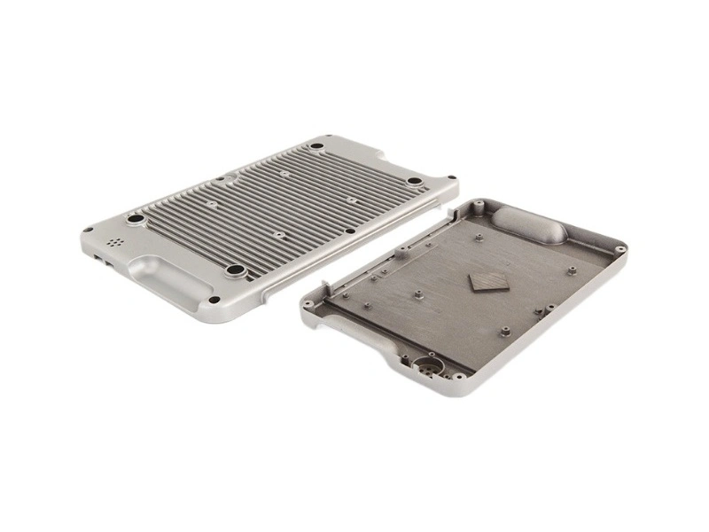
Zinc die casting parts are often used as assembly parts and appearance parts. Flash, burrs, hole position deviation or poorly planned parting lines can affect assembly efficiency and cosmetic acceptance. These risks should be controlled during tooling and sample validation, not only after mass production starts.
1. Control Flash and Burrs Through Tooling Planning
Zinc die casting tooling affects flash, burrs, parting line quality and visible edge conditions. Tooling review should include parting line position, mold fit, gate location, ejection and trimming requirements.
Tooling Area | How It Affects Flash or Burrs | Buyer Should Confirm |
|---|---|---|
Parting line position | Affects where flash or visible lines may appear | Whether the parting line is acceptable for appearance and assembly |
Mold fit | Poor fit can increase flash formation | Tooling precision and maintenance plan |
Gate location | Gate trimming can leave marks or burrs | Gate location away from critical cosmetic or assembly areas when possible |
Ejector pin position | Ejector marks may affect visible or contact surfaces | Acceptable ejector mark locations |
2. Control Design Features That Create Assembly Risk
Part design affects whether zinc die cast parts assemble smoothly. Draft angle, wall thickness, rib design, boss design, hole position and datum surfaces should be reviewed before tooling.
Design Area | Why It Matters | Risk if Ignored |
|---|---|---|
Draft angle | Helps parts release from the mold cleanly | Drag marks, deformation or surface damage |
Wall thickness | Affects filling, shrinkage and dimensional stability | Distortion, flash risk and poor fit |
Boss structure | Supports holes, threads and fastening areas | Weak threads, sink marks or cracking |
Rib structure | Supports stiffness without excessive thickness | Warping or assembly interference |
Assembly datum surfaces | Control how the part locates during assembly | Misalignment and inspection disputes |
3. Define Deburring and Edge Quality Requirements
Deburring requirements should be defined before production. Buyers should specify which edges are critical, which burr level is acceptable and which areas cannot have sharp edges or loose flash.
Deburring Item | Why It Matters | Buyer Benefit |
|---|---|---|
Critical edge marking | Shows where burrs can affect assembly or handling | Reduces assembly interference and safety issues |
Visible edge quality | Decorative parts need clean edges | Improves cosmetic acceptance |
Functional edge control | Burrs may affect mating parts or movement | Improves fit and product function |
Inspection standard | Clarifies acceptable burr size or appearance | Reduces supplier and buyer disputes |
4. Plan CNC Machining for Assembly Features
Some assembly features need CNC machining for assembly features. Machined holes, threaded holes, locating surfaces and datum faces should be planned before tooling so the supplier can prepare machining allowance, fixtures and inspection methods.
Assembly Feature | Why CNC Machining May Be Needed | Buyer Should Define |
|---|---|---|
Machined holes | Hole position and diameter affect assembly alignment | Hole tolerance and position requirement |
Threads | Thread quality affects fastening reliability | Thread size, depth and inspection standard |
Datum surfaces | Datums control assembly and measurement | Datum location and flatness requirement |
Locating features | Assembly fit depends on repeatable locating areas | Fit tolerance and mating part information |
5. Use Trial Samples to Validate Assembly
Trial samples help verify whether the part can assemble correctly before long-term production. Buyers should check hole position, thread fit, burrs, flash, parting line, cosmetic surfaces, coating impact and packaging condition.
Trial Sample Check | Why It Matters | Risk Reduced |
|---|---|---|
Assembly fit | Confirms the part works with mating components | Batch assembly failure |
Burr and flash level | Confirms trimming and edge control quality | Rework and cosmetic rejection |
Machined holes and threads | Confirms functional features meet requirements | Fastening or fit failure |
Surface appearance | Confirms parting line, gate marks and finishing quality | Appearance disputes after production |
6. Material Comparison for Quality Risk
A custom metal casting quality review can help compare zinc, aluminum and copper alloy routes. Aluminum die casting quality control often focuses on shrinkage, porosity and lightweight structures. Copper die casting machined parts often focus on functional surfaces, tool wear and machining accuracy.
7. Summary
Risk Area | How Buyers Can Reduce It |
|---|---|
Flash and burrs | Optimize parting line, mold fit, gate location and deburring requirements |
Assembly issues | Mark datum surfaces, machined holes, thread requirements and tolerance needs |
Cosmetic rejection | Confirm visible surfaces, parting line and ejector mark positions before tooling |
Batch instability | Use trial samples to validate assembly, machining and finishing before production |
In summary, buyers can reduce flash, burrs and assembly issues in zinc die casting parts by planning parting line position, gate location, draft angle, wall thickness, boss and rib structure, deburring requirements, assembly datums, machined holes, thread requirements and trial sample validation before long-term production.