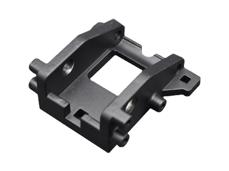
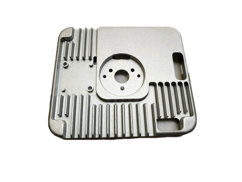
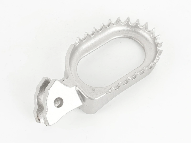
Zinc Alloy Die Casting Service for Precise Custom Metal Parts
A zinc alloy die-casting service is a strong route for precise custom metal parts when a stable design needs compact geometry, fine cast detail, repeatable interfaces or a decorative finish, and projected demand can justify dedicated steel tooling. Zinc alloys can fill intricate cavities and are commonly processed by hot-chamber die casting. Neither the alloy nor the machine automatically guarantees precision or a flawless plated surface.
The finished result depends on the specified zinc grade and purity, die layout, thermal state, shot settings, cavity condition, trimming, aging allowance, local machining and surface preparation. A buyer should define which dimensions control assembly, which surfaces are cosmetic, what loads and temperatures occur in service, and how the accepted part will be tested. The service quotation must cover that complete route rather than an unspecified casting.
Use zinc die casting when its near-net detail and finishing route create measurable product value. Reconsider it for large weight-sensitive structures, sustained loads at elevated temperature, frequently changing designs or products whose required material state cannot be demonstrated by the proposed alloy and process.

Start with function, not the zinc label
Send the supplier the controlled CAD model and drawing, but also explain the part's job. Mark mating hardware, moving contacts, fastener loads, electrical paths, hand-contact areas, visible zones and surfaces exposed to moisture, cleaners or abrasion. State the service temperature range and whether a load remains applied for long periods. Zinc alloys can creep under sustained stress, and the risk changes with alloy, stress, temperature, section and time.
A small lock component, connector body or control lever may exploit zinc's ability to cast thin local details, close feature spacing and clean net-shape edges. A large portable housing may be rejected on mass. A bracket that passes a short room-temperature pull test may still be unsuitable under continuous load near a heat source. Material and geometry decisions therefore need service-condition evidence, not a generic statement that zinc is strong.
Demand and design maturity matter as well. Tooling can make repeated small parts efficiently, but a late interface change may alter cavity steel, slides, trim tooling, fixtures and plating racks together. Compare realistic demand ranges and revision risk with CNC machining or another route. There is no universal quantity at which zinc die casting becomes economical.
Define precision by feature and inspection stage
Replace the word "precise" with controlled characteristics. Identify hole position, latch travel, gear center distance, connector alignment, flatness, thread engagement or cosmetic gap as applicable. Reference functional datums and state whether the requirement applies after casting, aging, machining, plating or assembly. The die-casting tolerance plan should distinguish as-cast dimensions from finished interfaces.
Zinc castings can reproduce detailed geometry, but dimensions still respond to cavity size, die temperature, tool wear, parting-line condition, ejection, trim and time after casting. If natural dimensional change matters to the assembly, agree when samples and production parts are stabilized and measured. Do not compare a warm first-off casting with an aged, plated production part as though they were the same inspection state.
Apply tight controls only where product function needs them. Blanket tolerances increase tool correction, sorting, CNC work and rejection without improving a hidden clearance surface. A useful drawing also gives separate appearance classes for primary, secondary and concealed surfaces. This prevents a minor ejector witness on an internal face from being judged like a plated handle surface.
Requirement | Project decision | Evidence before release |
|---|---|---|
Moving or locating feature | As-cast control versus local machining | Datum-based measurement and functional assembly test |
Sustained mechanical load | Alloy, section and service-temperature suitability | Test under defined load, temperature and duration |
Decorative plated face | Cavity finish, polish allowance and plating system | Approved limit sample under stated viewing conditions |
Corrosive or handled surface | Pretreatment, coating stack and edge coverage | Named exposure test on representative finished parts |
Electrical contact or grounding point | Selective plate, mask or post-finish operation | Resistance or continuity method in final assembly condition |
Repeated small-part demand | Cavity count, tool class and automation | Demand scenarios, capacity plan and cavity-specific trial data |
Select a zinc alloy by service and process
Zamak 3 is a common baseline for general zinc die casting because it combines established casting behavior, dimensional performance and finishing compatibility. Zamak 5 contains more copper and is often considered where added strength or hardness is useful, with tradeoffs that need review for the actual part. Zamak 7 is associated with high fluidity and ductility and may help delicate fill or finishing-sensitive designs. Zamak 2 provides a different strength, hardness and creep-resistance direction for specialized mechanical uses.
ZA-8 has higher aluminum content than the Zamak family and may be evaluated for higher mechanical or wear demands. Its machine route, process controls and finish must be confirmed with the supplier. Do not approve "zinc alloy" as an open material specification. The Zamak alloy selection guide can frame the comparison, but the drawing must name the controlling standard, grade and permitted alternatives.
High-purity control matters. Excess lead, cadmium, tin or other restricted impurities can damage long-term corrosion behavior in zinc alloys. Require the applicable chemistry limits, certificate and melt-control records; do not invent a universal recycled-content limit. Returned material policy, purchased ingot, contamination prevention and spectrometric checks should match the project's material and regulatory requirements.
Published room-temperature tensile values are not enough for a loaded latch, gear or bracket. The casting has local section changes, skin, porosity and a time-dependent service environment. Validate the property that controls failure using a representative specimen or part method with stated conditioning. Alloy substitutions require formal review of chemistry, casting behavior, dimensions, finishing and service tests.
Design for flow, release and tool access
Good zinc die-casting geometry gives metal a short, balanced path and lets the solid part leave the die without damage. Use practical draft, radii and section transitions. Support bosses and ribs without building unnecessary heavy junctions. Locate the parting line, gates, overflows, vents and ejector contacts away from protected cosmetic and functional zones where possible.
There is no universal minimum wall or smallest cast detail. Feasibility depends on alloy, distance from gate, flow splits, die temperature, venting, feature aspect ratio and the available machine. A thin wall beside the gate is not equivalent to the same wall beyond several turns. Ask the supplier to mark difficult fill paths and explain how the trial will verify complete fill and mechanical integrity.
Undercuts, cross-holes and reverse draft can require slides, collapsible elements or later machining. Each moving action adds tool cost, wear interfaces and maintenance. Compare a slide with redesigning the feature or machining it after casting. The zinc die-casting design guidelines help structure this feature-level DFM review.
Threads deserve a specific decision. Some external thread forms may be cast when release and use permit; internal threads, sealing threads and highly controlled engagement often need tapping, forming or inserts. State the thread standard, engagement, torque or pull requirement and plating condition. A thread gauge alone does not establish joint performance.
Understand the hot-chamber production route
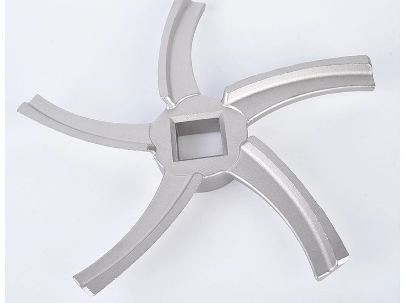
Many Zamak parts are made by hot-chamber die casting. The injection system operates in the molten metal, and a gooseneck/nozzle transfers alloy into the closed die. Zinc's comparatively low processing temperature makes this route practical and can support efficient repeated cycles. Cycle and capacity still depend on part mass, wall distribution, cavity count, cooling, slides, ejection and automation; they cannot be promised from material alone.
The die is prepared and brought to a controlled thermal state, then closes with slides in position. Metal is injected through runners and gates, pressure is applied during early solidification, and the shot cools before ejection. Gates, runners, overflows and flash are trimmed. The part may then be deburred, aged or stabilized as required, machined, polished, plated, coated and assembled.
Process controls should relate to named risks. Metal and die temperature, shot response, fill behavior, cycle interruptions and die spray can affect cold shuts, flow marks, porosity, flash and dimensions. Sample records must identify tool revision, cavity, machine, alloy heat or lot and downstream route. A good part selected from mixed cavities cannot qualify every cavity.
Build the tool for cavity condition and cosmetics
The tool controls geometry, but it also creates every visible surface and witness line. Confirm cavity count, tool steel and treatment, inserts, slides, cooling, venting, trim method, cavity identification and approved repair practice. The tooling plan should state ownership, storage, maintenance records and change authorization.
Tool finish matters when parts will be polished or plated. Scratches, erosion, soldered material, mismatch and poorly repaired steel may remain visible or become more obvious after a reflective finish. Define maintenance triggers from actual flash, dimensions and surface evidence. Tool-life estimates depend on design, steel, thermal cycling, alloy, process and care; treat them as planning assumptions rather than warranties.
Multi-cavity tools need cavity-specific validation. Runner balance and local cooling can create different fill or dimensions even when all cavities look alike. Keep cavity marks readable after finish, and retain measurement, defect and maintenance data by cavity. This supports targeted correction instead of sorting an unexplained mixed batch.
Separate casting defects from finish defects
Zinc castings can show cold shuts, flow lines, gas porosity, shrinkage, flash, drag marks, blisters or trim damage. The response depends on mechanism and location. Flow or vent changes do not solve a polishing scratch, and extra coating does not repair a cold shut that intersects a loaded feature. Establish defect zones and an escalation path before production.
Decorative plating magnifies substrate quality. Pits, pores, laps, parting mismatch and aggressive polishing can telegraph through copper, nickel, chromium or another specified stack. Surface preparation must remove residues without rounding protected detail or changing a datum. Rack contact and current distribution affect appearance; barrel processing changes part-to-part contact and handling risk. Select the route with the finishing supplier using representative geometry.
Do not ask a salt-spray result to prove every service condition. State the coating system, substrate, pretreatment, thickness or grade where relevant, test method, exposure, evaluation points and acceptance criterion. Wear, cleaners, fingerprints, galvanic contact and outdoor exposure may need different evidence. The zinc finishing comparison should be translated into a product-specific specification.
Plan local machining, inserts and assembly
Many zinc parts can retain substantial as-cast detail. Use CNC only for interfaces whose fit, surface or geometry cannot be controlled adequately in the released casting route. Possible operations include drilling, tapping, reaming, facing or slotting. The casting and machining route must define cast locators, finished datums, stock and fixture support before tool release.
Machining can expose subsurface porosity or break the protective casting skin. This matters around threaded ports, sealing areas and thin walls. Qualify the actual depth and sequence, then inspect in the finished state. Deburring and cleaning criteria need definition for mechanisms or connectors where chips and media can interfere with movement or conductivity.
Inserts may be cast in, pressed, staked or installed after finish depending on retention, temperature, coating and automation. Define pull-out, torque, position and electrical requirements. Assembly trials should use actual mating parts, fasteners, lubricants and finish thickness. If a coating stack changes a snap, hinge or sliding fit, a bare casting layout does not prove final function.
Validate appearance, dimensions and service together
Trial approval should identify the tool revision, cavity, machine, alloy lot, casting window and every downstream operation. Inspect fill and trim, then dimensions at the agreed time after casting. Run the approved polish, plate or coating route on representative cavities, and inspect appearance under documented lighting, distance and orientation. A hand-polished show sample is not a production finish standard unless its method is repeatable.
Functional validation belongs on finished parts. Test thread torque or pull, latch movement, connector fit, electrical continuity, coating adhesion, corrosion exposure or sustained load only where relevant to the product. Name the mating components, conditioning, load, temperature, duration, sampling and acceptance criteria. Avoid a generic "durability test" that cannot be repeated.
Release the process only after deviations and corrections are closed against the controlled drawing. Define first-off checks, cavity sampling, finish lot traceability, tool-maintenance verification and reaction to interruptions. Changes in alloy source, cavity steel, machine, polishing media, plating supplier, coating stack or fixture can invalidate prior evidence and require risk-based requalification.
Compare total cost and supplier responsibility
Separate one-time DFM, tool, trim die, fixture, rack, gauge and qualification costs from recurring alloy, casting, trim, deburr, machining, polish, plating, inspection, assembly, packaging and logistics. Decorative rejects discovered after several finish layers carry more accumulated cost than rejects contained after trim. Require defect and yield data by operation rather than one blended number.
A low tool price may hide weak cavity steel, difficult maintenance or inadequate cosmetic planning. A low casting price may exclude polishing, selective masks or final appearance inspection. Compare quotations in the same delivered condition, with the same demand scenarios and ownership terms. Define who pays when a substrate pore appears after plating or a finished dimension shifts because coating thickness was omitted.
An integrated supplier may simplify responsibility, while qualified specialists may provide the right process depth. Either model can work if revisions, acceptance standards, traceability and corrective action survive every handoff. Supplier selection should examine actual zinc alloy and finishing controls, not rely on a broad one-stop claim.
Send a complete zinc die-casting RFQ
RFQ input | Decision enabled | Ambiguity to remove |
|---|---|---|
Controlled 3D model, 2D drawing and revision | DFM, parting, slides, cavity and machining plan | Which file controls conflicting geometry |
Zinc grade and governing specification | Ingot, melt, chemistry and substitution control | Whether another Zamak or ZA grade is permitted |
Loads, temperature, environment and life | Creep, corrosion, wear and material validation | Short peak load versus sustained service load |
Functional features, datums and inspection stage | As-cast/CNC split, fixtures and gauges | Measurement after casting, aging, finish or assembly |
Cosmetic zones and approved finish system | Tool polish, preparation, rack/mask and visual inspection | View conditions, limit samples and allowed witness marks |
Demand range, batch pattern and program life | Cavity, automation, tool and capacity scenarios | Forecast versus committed purchase releases |
Validation, packaging and change control | Trial quantity, finish protection and production release | Which changes require approval or repeated tests |
Ask the supplier to return assumptions and exclusions. The response should identify the proposed process, machine and cavity arrangement, tool actions, visible gate/ejector zones, subcontracted finishing, inspection methods and trial plan. This exposes conflicts before steel is cut and allows a fair comparison of the finished-part offer.
Buyer decision
Choose a zinc alloy die-casting service when the product benefits from detailed near-net metal geometry, stable repeated demand and a finish route that has been designed with the casting. Lock the zinc grade and purity controls, define precision at the correct inspection stage, validate sustained service conditions, and approve cosmetic samples from representative cavities. The supplier should provide traceable evidence from tool through finish and assembly, not an unconditional promise based on zinc's general reputation.
FAQ