
What Design Details Help Zinc Die Casting Components Avoid Flash, Burrs and Deformation?
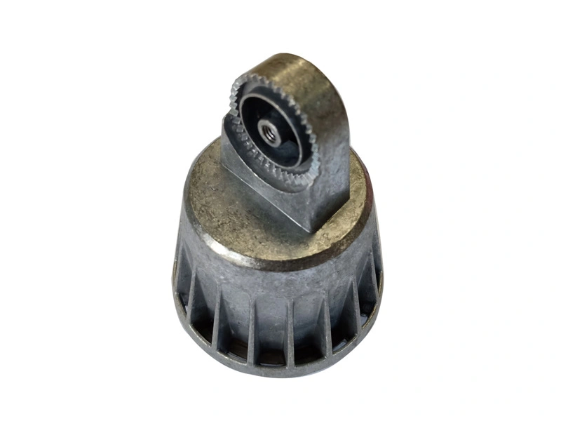
What Design Details Help Zinc Die Casting Components Avoid Flash, Burrs and Deformation?
Zinc die casting components can avoid flash, burrs and deformation by using balanced wall thickness, proper draft angles, suitable radii, controlled ribs and bosses, stable parting lines, good gate placement and planned trimming or post-processing. These details should be reviewed before tooling begins.
1. Why Flash, Burrs and Deformation Should Be Reviewed Before Tooling
Small zinc die casting components often include thin walls, holes, decorative details, snap-fit features and complex edges. These details can make the part useful, but they can also increase the risk of flash, burrs, deformation, ejector marks or unstable edges. If these risks are found only after tooling, correction can be expensive and slow.
A better approach is to review the zinc die casting component design before mold manufacturing. Neway can support design review for zinc die cast components and engineering evaluation to reduce manufacturing risk early.
Defect Risk | Possible Design Cause | Prevention Method |
|---|---|---|
Flash | Complex parting line, poor shut-off area or tooling wear. | Tooling review, parting line planning and maintenance. |
Burrs | Sharp edges, hole edges or insufficient trimming plan. | Trimming, tumbling and deburring control. |
Deformation | Uneven wall thickness, large flat areas or weak structure. | Rib design, wall optimization and balanced ejection. |
Ejector marks | Ejector locations placed on visible or functional areas. | Tooling planning before mold build. |
Poor edge quality | Post-processing not planned for complex edges. | Tumbling, deburring or controlled blasting. |
2. How Design Details Reduce Defect Risk
Balanced wall thickness helps reduce shrinkage, warpage and internal stress. Proper draft angles help the component release from the mold more smoothly. Fillets reduce stress concentration and improve metal flow. Ribs and bosses should support strength without creating heavy local thickness. Gate and ejector locations should be planned to avoid visible surfaces and critical assembly areas.
For zinc die casting components with small holes, thin features, snap-fit structures or detailed edges, these design details can strongly affect batch stability and post-processing workload.
3. How Tooling and Maintenance Affect Flash Control
Flash is often connected to the parting line, local shut-off design, mold clamping, insert fit and long-term tooling condition. Even if samples are acceptable, flash may increase later if tooling wear is not controlled. That is why tooling for zinc die casting components and tooling maintenance should be part of production planning.
Buyers should also define where flash is unacceptable, especially on cosmetic faces, mating surfaces, sliding areas and edges touched by users.
Manufacturing Area | Control Focus | Buyer Benefit |
|---|---|---|
Parting line | Placement away from visible or mating surfaces. | Reduces cosmetic and assembly problems. |
Gate location | Flow balance and mark position. | Improves filling and appearance control. |
Ejector layout | Balanced ejection and mark control. | Reduces deformation and visible marks. |
Tooling maintenance | Wear, flash growth and insert condition. | Maintains long-term edge quality. |
Post-processing | Burr removal and surface cleanup. | Improves assembly, appearance and handling safety. |
4. How Post-Processing Helps Edge and Surface Quality
Some edges and small details still require trimming, deburring, tumbling for zinc die cast parts or sand blasting for die cast components. These processes can help remove burrs, smooth edges and prepare surfaces for finishing.
However, post-processing should not replace good design and tooling. If burrs, flash or deformation are caused by poor component design or unstable tooling, post-processing may only hide the problem temporarily. The best result comes from combining design review, tooling planning, casting control and finishing strategy.
Summary
Buyer Concern | Recommended Action |
|---|---|
Flash appears on visible or mating surfaces. | Review parting line, shut-off design and tooling maintenance. |
Burrs affect assembly or hand feel. | Plan trimming, tumbling, deburring and edge quality standards. |
Components deform after casting. | Optimize wall thickness, ribs, bosses and ejection balance. |
Complex features may create production risk. | Use design review and tooling planning before mold manufacturing. |



