
45 Steel Yield Strength: 355 MPa After Quench and Temper
45 steel yield strength reaches 355 MPa on this bracket only after a quench and a temper, and the drawing carries that figure as a target, not a property that arrives with the grade. GB/T 699-2015 settles the steel and its quenched and tempered condition. Whether a 25–30 mm section hardens through is decided by how the thick section is fed, the quench and temper windows, and a cast-on test bar pulled to ASTM A370. Casting material selection sets the starting point for all four.
What GB/T 699-2015 Fixes and What It Leaves Open
The standard fixes the grade, the analysis behind it, and the ordered condition, quenched and tempered. A certificate issued to GB/T 699-2015 answers a chemistry question, not a section question. The same 355 MPa is asked of a 12 mm wall and of a 30 mm boss, a factor of two and a half in section.
What stays open is the 25–30 mm load path: hardenability there, the cooling the core sees, and how that melt answers the temper. The drawing closes the gap by placing 355 MPa in the tolerance block and naming a test method, while a certificate alone leaves it open on a metal casting order.
355 MPa Is a Target, Not a Grade Property
The part specification marks 45 steel yield strength at 355 MPa as a design target still to be confirmed, and the drawing writes it as a floor, ≥355 MPa. A floor is an acceptance value, the minimum a passing bar reads, and says nothing about the typical result. Filing it as a material property is where orders go wrong.
Hardness is a window, HB 220–250, 30 points across; yield is a line with no width. The window absorbs the scatter of a furnace load, while the line has to be demonstrated once per batch by a tensile pull. The demonstration costs a bar, a hardness check and a furnace record, which a static load case with a generous section does not need.
25–30 mm Sections Against Hardenability
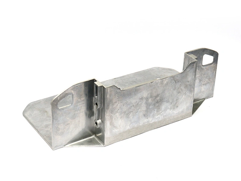
The bracket runs a 25–30 mm section where the bolts pass, with 8–12 mm walls between. Work the ratio on the drawing values: 25 ÷ 12 ≈ 2.1 and 30 ÷ 8 = 3.75. The thick end freezes and cools last, so its core meets the quench later and slower than the skin of a wall.
Slow cooling at the core is the first failure mode listed for this part. Austenite that never becomes martensite cannot be recovered by tempering, so body yield stays under 355 MPa while the skin reads hard. An example record shows the gap: a bar that passed while the body came in short, fixed by a cast-on test bar, a riser and a temper adjustment. Adding wall to the boss only slows the core further.
The Quench and Temper Window
Quench at 840–860 °C and temper at 550–600 °C. The quench window is 20 °C wide, the temper window 50 °C, two and a half times wider. Austenitizing has to hit a narrow band without growing the grain, while hardness falls off gently across the temper range.
Read the pair as one setting. Run the temper at the top of its range and hardness drops through HB 220–250, with yield following it down. A batch that holds both windows but skips the bar has evidence for two of the four lines below.
Variable | Value | Unit | Evidence |
|---|---|---|---|
Quench temperature | 840–860 | °C | Quench chart for the load |
Temper temperature | 550–600 | °C | Temper chart for the load |
Hardness | 220–250 | HB | Reading on the body |
Yield strength | ≥355 | MPa | Tensile pull to ASTM A370 |
Hardness HB 220–250 as a Body Check
Hardness is the only strength check that touches the bracket itself. It reads the skin of the 25–30 mm section in seconds and can be repeated at several points. The test bar reads the melt, a hardness reading reads the section, and that difference is why both exist.
The reading is not a yield value. Nothing in the quench and temper data converts HB 220–250 into 355 MPa, and a figure inside the band is consistent with the target rather than proof of it. The band spans 30 points, about 14% of the 220 floor, so a bracket can pass at the bottom of the window.
Depth is the weak point: an indenter sees a shallow layer, and a soft core under a hard skin reads like a sound section. The test points and the accept rule are still pending confirmation with the foundry.
Test Bars: What They Cover
A cast-on test bar is poured from the same ladle as the bracket and stays with it through the quench and the temper. Pulled to ASTM A370, it reports the yield that the melt and the furnace load actually produced. That is the closest thing to a body value a batch can carry.
What the bar cannot do is sample the core of a 25–30 mm boss. Its own section is smaller, so it cools faster and hardens more readily than the metal it stands for. Pour the bar from another melt, or temper it separately, and the mechanical property testing record describes something other than the bracket.
Wall 8–12 mm and the 25–30 mm Boss
The two sections do different jobs. The 8–12 mm wall sets fill and cooling across 180×120×60 mm; the 25–30 mm boss carries the bolt load. Push the ratio to its ends and one bracket spans 2.1:1 to 3.75:1, depending where the drawing lands.
That ratio decides which defect appears first. A high ratio lets the wall set before the boss, and the boss then shrinks without a liquid path back to the riser. The mass band is wide for a reason: 1.8–2.5 kg is 0.7 kg, about 39% of the low end, and geometry moves it.
Feature | Value | Unit | What it sets |
|---|---|---|---|
Wall | 8–12 | mm | Fill and cooling rate |
Thick section | 25–30 | mm | Feeding and hardenability |
Finished mass | 1.8–2.5 | kg | Fixture load and handling |
Hole pitch | ±0.2 | mm | Bolt-up with the frame |
Face flatness | 0.1 | mm | Contact under bolt preload |
Heat-Treatment Distortion Eats Stock
A quench from 840–860 °C on a 180×120×60 mm bracket moves the shape. Thin walls cool first, the boss last, and the difference shows up as bow and twist on the mounting face. That face has 0.1 mm of flatness to hold after machining, one part in 1,800 across a 180 mm face, so the stock has to cover movement larger than that.
Blasting takes metal as well. Sa 2.5 to ISO 8501-1 is a cleanliness grade, and the route blasts before it cuts, so one stock allowance has to cover both the blast and the distortion. Cutting after blasting keeps hole pitch ±0.2 mm from drifting; straightening after temper adds stress and returns no stock.
Phosphating or Black Oxide, Not "Passivation"
The part specification lists passivation under surface treatment, and its note says something narrower. Passivation waits for the customer drawing, and carbon steel normally goes to phosphating or black oxide. Both statements describe the same bracket, so the drawing decides.
Three words, three processes, three acceptance criteria on the surface finishing route. A phosphate coating is judged on crystal structure and coating weight, black oxide on color and oil film, passivation on a passive film that forms by itself on stainless. One word for all three leaves an inspector nothing to check, and a batch finished to the wrong one is a reject at goods-in.
When 45 Steel Loses to Another Route
Two alternatives sit in the part specification: lost-wax casting, the customer's original route, and a weldment. 45 steel loses when the 25–30 mm section needs a riser the mold layout cannot fit, or when the bracket is a plate with ribs a welder builds from standard stock.
A weldment moves the thick section out of the mold and brings heat-affected zones, distortion along the welds and a datum that no longer matches the casting drawing. Switching routes is a drawing change, not a sourcing change, and a metal casting supply case shows how the casting route carries its records from callout to batch. A grade picked for hot hardness in a die answers a different question, so tool steel heat treatment is not a template here.
FAQ
What are the best practices for designing parts with varying wall thicknesses in metal casting?
How does alloy selection affect design constraints and casting precision?
What testing methods do you use to validate long-term part performance?
Do you offer quality inspection reports and material certifications for each batch?
What tolerances can you achieve in CNC post-machining after casting?
.webp)
.webp)