Electric Vehicle Castings: How Buyers Balance Weight, Structure and Production Quality
Electric vehicle castings are best selected by mapping each component's function to a material, casting route, secondary-operation plan and evidence package. A bracket that transfers assembly loads, a motor housing that locates rotating interfaces and a coolant enclosure that must remain sealed create different risks even when all three are aluminum.
Buyers therefore need more than a lightweighting argument. They need defined load paths, allowable mass, thermal duty, sealing interfaces, corrosion exposure, mating materials, annual demand and lot pattern. Those inputs determine whether casting is appropriate, which alloy family deserves evaluation and where machining, finishing or risk-selected inspection belongs.
No general process statement establishes service suitability. Structural, thermal, electrical isolation, ingress or durability conclusions require validation against the project drawing, assembly, operating envelope and applicable buyer requirements. The useful sourcing question is whether every important function has a corresponding process control and release decision.
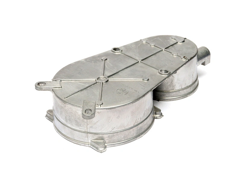
Which Electric Vehicle Parts Are Commonly Produced as Castings?
Castings for electric vehicles commonly fit four application groups: structural brackets, functional housings, thermal-management parts and connection hardware. Casting is attractive when a component benefits from three-dimensional ribs, bosses, mounting points, passages or integrated interfaces at a repeatable production volume. The category name does not determine the process; geometry, loads and evidence needs do.
Structural brackets may consolidate attachment points and use rib networks to carry assembly loads. Their main risks are local stress, distortion at bolted interfaces, insufficient section around bosses and corrosion at joints. Acceptance may involve dimensional evidence and load or assembly validation selected for the actual function. Functional classification, limits and approval remain project-specific.
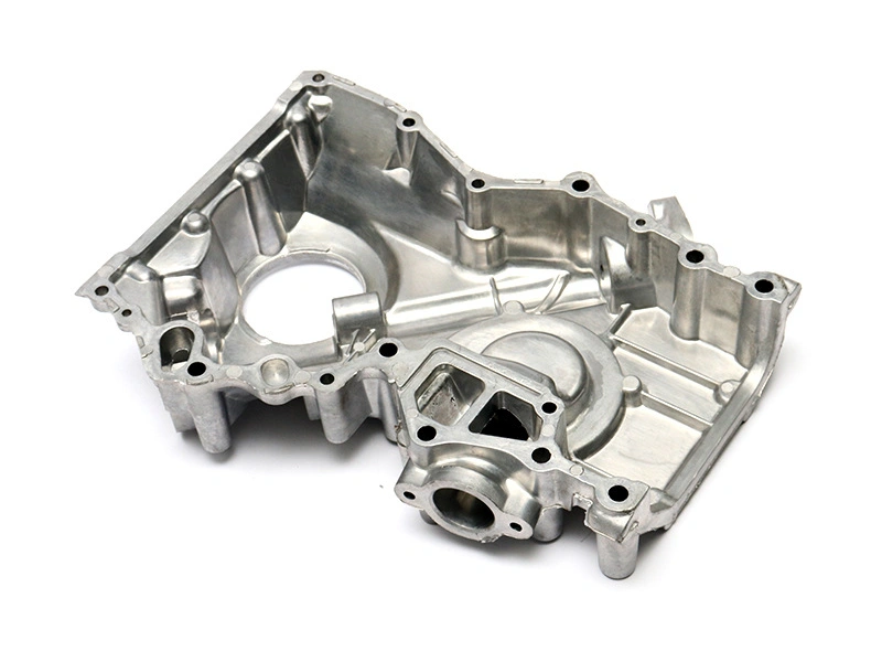
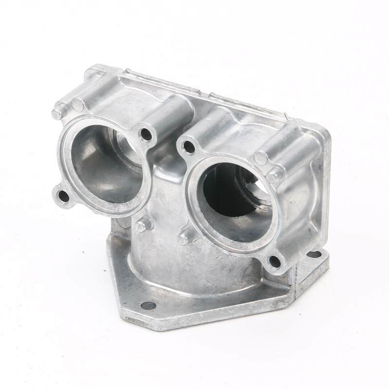
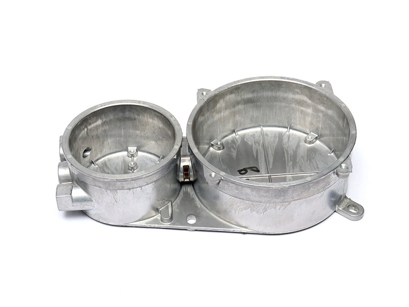
An EV motor housing casting, inverter enclosure or charger housing may locate covers, connectors, bearings, power modules or sealing elements. The relevant risks can include bore alignment, flange flatness, machined leak paths, thermal-interface flatness and galvanic contact. EV aluminum castings can support complex housing geometry, but the buyer still has to qualify the proposed alloy and process for the delivered part condition.
EV Component Group | Main Function | Casting Requirement | Main Project-Specific Validation |
|---|---|---|---|
Battery module bracket or equipment carrier | Transfer assembly loads and hold interfaces | Rib continuity, boss support, controlled flatness and low mass | Datum-based dimensions plus specified assembly or load evidence |
Motor, inverter or charger housing | Locate internal parts and close an enclosure | Stable bores, flanges, connector zones and machining stock | Dimensions, interface checks and leak evidence when sealing is functional |
Thermal plate or heat-dissipation carrier | Move heat through a defined interface | Controlled thermal land, fins or passages with manageable distortion | Flatness, material state and thermal or flow test when required by the design |
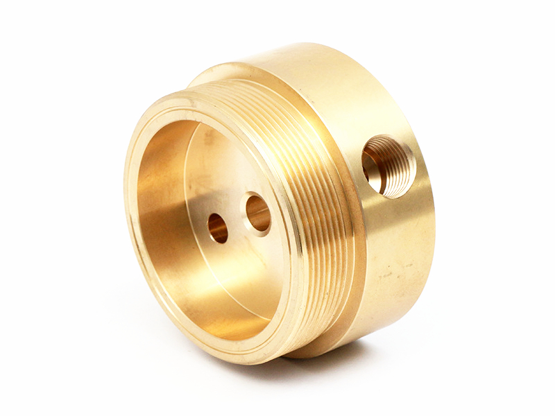
Connector mount or cable support | Locate and protect connection points | Boss integrity, thread strategy, edge control and corrosion protection | Position, thread or insert checks and applicable environmental evidence |
EV thermal management castings need an unbroken heat path and controlled contact surface; intricate external fins alone do not prove thermal performance. Connector mounts need stable location and suitable protection around dissimilar fasteners. For every group, the validation column should be converted into drawing CTQs, sample conditions, methods and acceptance limits owned by the project.
How Buyers Choose Between Aluminum and Other Casting Materials
Aluminum is frequently evaluated because it combines low density, useful thermal conductivity, corrosion-management options and established casting routes. Yet aluminum is not the automatic answer for every EV component. Material screening should compare finished-part mass, required section size, stiffness, strength, heat flow, electrical or magnetic constraints, corrosion system, joining method and total production route.
A denser alloy may still fit a compact connector or small precision mechanism when thin sections, local strength or finish requirements reduce total envelope. Magnesium may merit evaluation where mass is dominant, but corrosion, joining, finishing and process-control implications need project review. Ferrous castings can remain relevant where wear, stiffness, temperature exposure or cost at the required geometry outweigh mass. Conductive copper alloys serve specialized electrical or thermal roles but bring their own process and cost constraints.
The comparison must use the finished component, not raw density alone. A low-density material that needs thicker walls, inserts, extensive machining or a complex coating stack may lose part of its advantage. Conversely, a cast geometry that integrates bosses and thermal features may reduce separate parts and joints. The buyer should compare CAD mass, minimum practical sections, downstream operations, joining hardware and validation cost for each candidate route.
Automotive aluminum references can provide context for common casting and machining considerations, but they cannot qualify an EV application. Final selection depends on the named standard, temper or delivered material condition, drawing requirements and evidence from representative parts.
Which Aluminum Alloys Fit EV Casting Requirements?
A356, A380/ADC12 and A360 represent different alloy and process choices, not interchangeable labels. A356 is commonly associated with gravity or low-pressure casting routes and can be considered where heat-treatment response, section behavior and structural-property requirements align with that route. The exact A356 condition matters, so chemistry, heat treatment, mechanical-property basis and sampling must be stated.
The A356 casting route may suit a bracket or housing when the design and production volume support its filling and solidification characteristics. It should not be described with invented universal strength, elongation or thermal values. Those properties vary with specification, temper, section, process and test location, and a project should use the governing material standard and agreed evidence.
A380 aluminum die casting is often screened for complex high-pressure die cast geometry and production efficiency. ADC12 is frequently compared with A380, but they come from different standards and are not automatically equivalent. Buyers should confirm chemistry limits, required properties, corrosion and finish behavior, and whether the drawing names one grade or permits an approved alternative.
A360 aluminum die casting can enter the shortlist where corrosion behavior, fluidity or application-specific performance justifies evaluation. It is not universally superior to A380, ADC12 or A356. Tooling behavior, die-soldering tendency, casting window, machining response, finish route and material availability all belong in the decision.
Alloy Family | Route Often Evaluated | Useful Screening Question | Approval Evidence to Define |
|---|---|---|---|
A356 | Gravity or low-pressure casting, depending on geometry and source | Do section behavior and specified delivered condition support the structural and thermal requirements? | Named standard, chemistry, heat-treatment state when applicable and representative material results |
A380 or ADC12 | High-pressure die casting | Does fill capability support the geometry while porosity, sealing and downstream needs remain manageable? | Exact grade standard, approved substitution rule, lot identity and risk-based part evidence |
A360 | High-pressure die casting | Do its route-specific casting and corrosion trade-offs match the environment and supplier process? | Exact material definition, process feasibility and finish or environmental evidence as specified |
A sound alloy decision is therefore a requirement-to-evidence decision. Freeze the standard designation and allowed condition, then confirm that tool design, process, machining, coating and inspection plans all refer to that same material definition.
How Casting Design Balances Lightweighting and Structural Stiffness
Lightweight EV cast components do not result from thinning every wall. Buyers and casting engineers first identify how loads move between mounting points, bearing seats, fasteners, covers and adjacent structures. Material can then be placed along those paths through ribs, returns, section depth and supported bosses while lower-demand zones remain thinner.
Wall transitions matter because isolated heavy sections cool differently from nearby thin walls. Abrupt changes around bosses, rib intersections and sealing flanges can encourage shrinkage risk and distortion. Gradual transitions, cored relief where feasible and rib proportions compatible with the selected casting route can reduce those conflicts. Manufacturability review must also consider fill distance, venting, ejection, draft and access for trimming.
Ribs increase bending stiffness efficiently when they connect meaningful load paths, but dense rib grids can create thermal nodes, obstruct die flow or complicate finishing. Bosses need enough support to carry assembly loads without creating unnecessary mass. A sealing flange may need local section and machining stock, yet excessive stock can increase machining time and expose internal discontinuities.
Stiffness and distortion should be evaluated in the delivered condition. Clamping during machining can flatten a flexible casting that springs back after release. Coating bake or assembly torque can change measured shape. Where these effects are relevant, the project validation plan should define free-state versus restrained measurement, fixture condition, temperature and assembled-state checks.
Optimization ends with evidence, not a visual judgment. Simulation may help compare concepts, while trial dimensions, section checks and specified structural tests address the final geometry and process state. Neither analysis nor a sample result should be generalized beyond its assumptions, material condition and load case.
Why Porosity and Leak Paths Matter in EV Housings
Porosity matters differently in a dry structural bracket and a sealed EV housing. Gas entrapment, shrinkage, oxide films or local process instability can create discontinuities, but the functional consequence depends on location, size, connectivity and remaining section. A noncritical internal indication is not automatically a leak; a connected path opened by machining can be.
EV battery housing castings, motor housings and thermal enclosures may include perimeter seals, ports, plugs, covers or fluid passages. Their pressure boundary should be mapped from the casting through every machining and assembly operation. Gates, overflows and vents are then developed around fill and air evacuation, while local wall transitions and machining allowance are reviewed for solidification and exposure risk.
Vacuum assistance or optimized venting can reduce certain gas-related risks when compatible with the part and process, but neither is a universal guarantee. Process settings must be evaluated with tool thermal balance, fill behavior, metal handling and cavity condition. Impregnation, where permitted, is a separate disposition or process choice and should not conceal an undefined acceptance basis.
Risk Location | Potential Defect or Leak Mechanism | Process or Design Control | Risk-Selected Verification |
|---|---|---|---|
Machined sealing flange | Machining intersects connected subsurface porosity or leaves incomplete cleanup | Stock map, smooth section transition, fill/vent review and stable machining datum | Surface inspection, flatness and leak test when the flange forms a specified boundary |
Port or threaded boss | Heavy local section shrinks or drilling opens a path to the wall | Supported boss, controlled section, suitable core or stock strategy and tool thermal control | Wall/position evidence and final-condition leak or thread checks as required |
Long thin-wall housing region | Air entrapment, cold flow or oxide-related discontinuity | Gate, overflow, vent/vacuum and process-window development | Visual, section, X-ray or other examination only where the risk plan justifies it |
Cover joint and fastener zone | Distortion, surface damage or assembly load interrupts gasket compression | Flange stiffness, protected surface, datum plan and controlled assembly inputs | Flatness, surface condition and assembly-level validation to the specified method |
Leak-test method, medium, pressure or vacuum level, stabilization, duration, allowable rate and sample plan come from function and buyer requirements. X-ray, computed tomography, sectioning or pressure-decay testing should be selected for a defined question. No single method proves every structural and sealing requirement.
How CNC Machining Completes EV Cast Components
Casting forms near-net geometry; CNC machining establishes interfaces whose accuracy, texture or geometric relationship cannot reliably remain as-cast. Typical electric vehicle die cast parts may need machined sealing faces, bearing bores, locating pilots, precision holes, threaded ports and thermal-contact lands. External ribs and nonmating surfaces often remain as-cast.
The machining plan begins with datum transfer. Cast pads or repeatable surfaces locate the first setup without relying on flash, ejector marks or unstable thin walls. That setup creates final datums, and later operations reference them. Fixture supports should sit near load paths, while clamp forces avoid bending a compliant housing into a temporary shape.
Machining stock must cover normal casting variation without creating excessive removal. A stock map around bores and flanges helps identify thin remaining walls, incomplete cleanup and porosity-exposure risk before tool release. Cutter access, chip evacuation, deburring and cleanliness also matter around channels, threads and enclosed cavities.
Inspection must match the datum scheme and final condition. CMM can be appropriate for related positions and profiles; gauges may be more efficient for production interfaces; surface texture or flatness may need dedicated methods. The drawing and control logic should identify which features are checked after machining, finishing or assembly and at what project-defined frequency.
How Surface Protection Changes in Salt, Heat and Galvanic Environments
Surface protection starts with exposure mapping rather than a finish name. Road salt, humidity, retained water, thermal cycling, cleaning chemicals and contact with steel or copper can create different corrosion mechanisms. Geometry that traps electrolyte, damaged coating edges and unisolated dissimilar-metal joints may dominate performance even when the base aluminum has useful corrosion resistance.
A post-process specification should define cleaning and pretreatment, coating family, thickness or coverage criteria where applicable, cure condition, appearance zones, masks and protected threads or electrical contacts. Coating build on a gasket land or locating bore can change assembly fit, so the drawing should state whether dimensions apply before or after finish.
Galvanic control may combine material pairing, isolating washers or sleeves, sealants, drainage and coating continuity. Masking bare contact zones for grounding or heat transfer changes the corrosion map and needs its own boundary treatment. Fastener coatings and assembly damage should be considered with the complete joint, not only the casting.
Environmental validation is project-specific. Salt spray, cyclic corrosion, humidity, thermal cycling, adhesion or coating-thickness checks answer different questions under defined conditions. A single test duration is not a universal service-life claim. Buyers should tie each requested result to exposure, sample preparation, acceptance limits and the delivered assembly state.
Engineering Scenario: Battery Module Bracket With Flatness and Corrosion Risk
Consider an aluminum battery module bracket with a thin outer wall, intersecting ribs, four mounting bosses and a broad assembly face. The assembly face must locate mating hardware without rocking, while exposed regions require a specified protective coating. The design target is low mass with sufficient stiffness under the project's defined mounting and service loads.
Early samples show that the rib intersections and boss sections cool differently from the thin wall. Free-state flatness at the assembly face varies, and hard clamping during machining temporarily hides part of the distortion. The engineering response can combine smoother wall-to-rib transitions, local section relief where feasible and fixture supports aligned with the intended datum structure.
Three stable cast pads become the first machining references. The setup creates the functional assembly datum and finishes only the named mounting lands. A stock map confirms cleanup without unnecessarily cutting the whole face. Measurement is recorded both after unclamping and in any specified inspection restraint so the result corresponds to the drawing definition.
The coating plan masks the finished mounting lands and threaded interfaces. Mask edges are positioned away from water traps where practical, and the drawing defines acceptable boundary condition. The related A356 battery module bracket reference may inform DFM questions, but alloy, application and performance still require confirmation for this bracket's specification.
A small validation lot can then test the revised route before repeat orders. The evidence set may include material identity, free-state flatness, mounting-land position, coating coverage and assembly or load checks selected by the buyer. Approval applies to the recorded drawing revision, material condition, tool state, machining fixture, coating route and tested conditions; it does not establish untested vehicle-level behavior.
What Inspection Evidence Should EV Casting Buyers Request?
EV casting buyers should request evidence in proportion to each CTQ and failure consequence. A material record answers alloy identity; dimensional results answer geometry; leak data answer a defined sealed-boundary condition; coating records answer the specified finish route. Asking for every available report can add cost without closing the actual risk.
Start with a characteristic matrix that names requirement, revision, sample state, method, acceptance limit, frequency and reaction. The matrix should distinguish casting dimensions from machined and finished dimensions. It should also identify destructive methods, cavity coverage and the disposition authority for nonconforming results.
Evidence Class | Risk It Addresses | Evidence Definition | Release Boundary |
|---|---|---|---|
Material and lot | Wrong alloy, condition or unlinked source lot | Specification, heat/lot identity, chemistry or property records as contractually required | Applies to identified material and represented parts |
Dimensional | Mislocated interfaces, flatness, wall or machining-stock error | Datum-based report, method, sample/cavity identity and part condition | Applies to measured characteristics and sample state |
Internal quality | Functionally relevant discontinuity or leak-path potential | Risk-selected X-ray, sectioning, CT or other method with defined zones and criteria | Does not replace function testing unless the project establishes correlation |
Leak or function | Failure of a specified sealed, flow, assembly or load condition | Finished sample state, fixture, medium/load, duration, limit and result | Supports only the stated condition and represented configuration |
Coating and corrosion | Coverage, adhesion, thickness or environment-specific degradation | Batch route, preparation, masks and specified test result | Applies to the tested substrate, preparation and coating system |
Traceability and change | Unclear material, cavity, process or revision history | Lot links, tool/cavity state, downstream batches, deviations and approved changes | Supports reconstruction to the retention level agreed with the buyer |
The available testing equipment overview can help buyers discuss measurement options, but equipment presence is not evidence that every method applies or that a particular part has passed. Method suitability, calibration status, programming, fixturing, sampling and acceptance remain part of the project plan.
PPAP, a control plan, capability evidence or a buyer-specific submission should be requested only when the governing customer or project requirement calls for it. Define the required level, content, approving party and resubmission triggers. The document name never substitutes for clear CTQs and technically relevant results.
How a Casting Supplier Supports EV Parts From Trial to Repeat Production
A casting supplier supports EV parts by maintaining a traceable decision path from requirements to a stable repeat-order configuration. The workflow begins with an indexed drawing and requirements review, not a broad capability statement. Open items should cover load and thermal assumptions, sealing boundary, corrosion exposure, material standard, volume pattern, finished scope and applicable buyer documentation.
DFM converts those inputs into a proposed casting route, tool concept, stock map, datum plan, finish map and risk-based evidence plan. Tool trials then test fill, ejection, section behavior and preliminary dimensions. Machined and finished samples answer downstream interface questions. Each stage should state what has been demonstrated and what remains open.
Supplier Stage | EV-Specific Decision | Stage Evidence | Release Decision |
|---|---|---|---|
Requirement and application review | Identify structural, thermal, sealing, corrosion and volume risks | Indexed inputs, CTQ list, open-item register and application risk map | Requirements are sufficient to compare material and process routes |
Material and DFM review | Select a candidate alloy/process and connect geometry to manufacturing controls | Material definition, wall/rib/boss review, fill/vent concept, stock and datum maps | Buyer authorizes the documented route for tooling or further validation |
Tool trial | Establish an initial operating window and identify defect or distortion risks | Tool/cavity state, recorded settings, sample sequence, observations and dimensional results | Corrections close named trial risks before finished-part evaluation |
Machining, finish and function trial | Confirm final interfaces, leak boundary, coating masks and assembly condition | Fixture/program state, finished dimensions and specified leak, coating or function results | Delivered configuration meets the agreed sample acceptance plan |
Small production-intent run | Evaluate normal handoffs, cycle, sampling, traceability and packaging | Lot route, CTQ results, nonconformance closure and pack evaluation | Buyer releases repeat production under stated conditions |
Repeat order and change review | Preserve the approved state or evaluate a proposed change | PO/revision match, material/tool status, change impact, maintenance and lot records | Run current state or approve a validated successor state |
A mass-production planning discussion should connect forecast and lot pattern to cavities, maintenance, inspection frequency, downstream capacity and traceability. It should not promise unlimited consistency. Repeat orders require confirmation that drawing revision, material source, tool state, machining program, coating route and acceptance methods remain compatible with the approved baseline.
Changes in alloy source, die insert, gate or vent geometry, heat treatment, machining fixture, program, coating preparation, test method or production location need an impact review. Revalidation can be focused when the effect is technically isolated, or broader when several functions may change. Where a buyer requires PPAP, control-plan updates or another formal submission, the agreed change triggers govern.
The strongest sourcing package is therefore a linked chain: application requirement, identified risk, selected process control, representative evidence and named release authority. That chain lets buyers compare electric vehicle castings on engineering fit and repeat-production discipline while keeping every structural, sealing, thermal and corrosion conclusion inside its project-specific validation boundary.
FAQ