Rapid Prototyping Service for Precise Metal Casting Parts

Rapid prototyping for precise metal casting parts works best when the prototype route is selected from the decision it must support. A printed model can reveal an assembly clash. A machined metal part can support an early load or thermal test. A sand or investment casting in the intended alloy can reveal some alloy and machining behavior. A bridge-tool or production-tool sample is needed to study die filling, ejection, casting skin, cavity variation, and process-specific porosity. No single “high-fidelity prototype” proves all of these.
The practical goal is not to make the first sample look as close as possible to the final part. It is to buy the right evidence before the next expensive decision. That may mean using two inexpensive routes in sequence rather than one elaborate prototype that still cannot answer the production question. A clear validation plan keeps rapid prototyping from becoming a display exercise and turns it into controlled risk reduction for a casting program.
Begin with the question, not the process
Write one primary question for each prototype build. Does the enclosure fit the electronics and connector stack? Does the bracket carry the target load without excessive deflection? Can the intended alloy be machined and coated as specified? Will the die-cast geometry fill, release, and remain within the required datum relationships? Will a pilot batch support assembly training or a field trial?
These questions require different evidence. If the purpose is assembly, exact cast microstructure may be irrelevant, while hole position and external envelope matter. If the purpose is fatigue, material route, surface, defects, and load fixture become central. If the purpose is tool release, a substitute process can help with geometry but cannot validate gating, vents, overflows, ejector marks, or cavity compensation.
Define acceptance before requesting a quote. Specify dimensions or fit conditions, functional loads, leak or thermal duty, appearance zones, surface finish, material state, quantity, documentation, and the decision that follows a pass. Otherwise, prototype inspection can become a subjective review with no agreed path to the next stage.
Use a prototype fidelity ladder
Prototype fidelity has several independent dimensions: geometry, material chemistry, material condition, manufacturing process, surface, dimensions, assembly, and quantity. A sample may be highly faithful in one dimension and deliberately different in another. For example, a CNC-machined A380 blank may use the nominal alloy but cannot reproduce pressure-die-cast flow, skin, residual stress, or discontinuity distribution.
Prototype route | Good evidence | Does not prove | Typical next decision |
|---|---|---|---|
Polymer 3D print | Envelope, fit, ergonomics, access, assembly sequence | Metal stiffness, heat transfer, castability, coating on cast alloy | Revise package or advance to a functional sample |
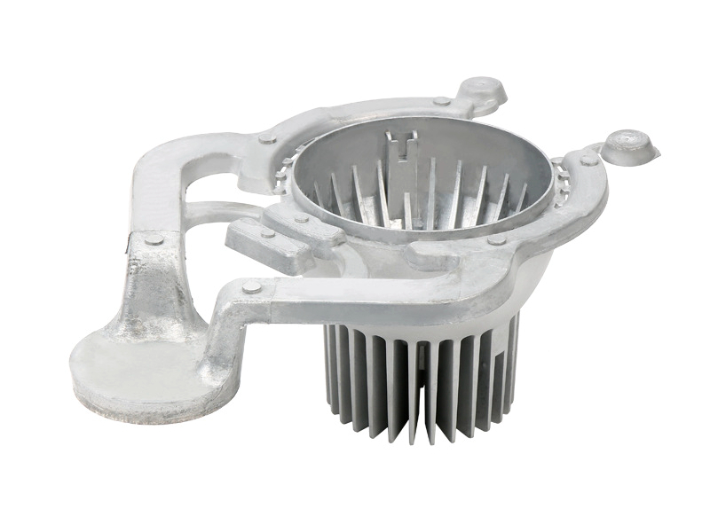
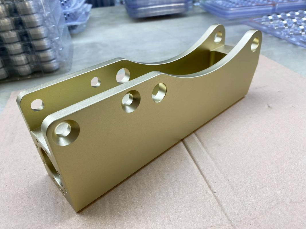
CNC-machined metal prototype | Metal mass, preliminary load/thermal behavior, machined interfaces | Casting fill, as-cast properties, surface, porosity, ejection distortion | Confirm product architecture or select a casting trial |
Sand/investment casting in intended alloy | Selected alloy and finish behavior, cast-metal machining, some functional tests | Pressure-die-cast microstructure, thin-wall fill, production die marks and cycle | Confirm alloy/function or proceed to die-based validation |
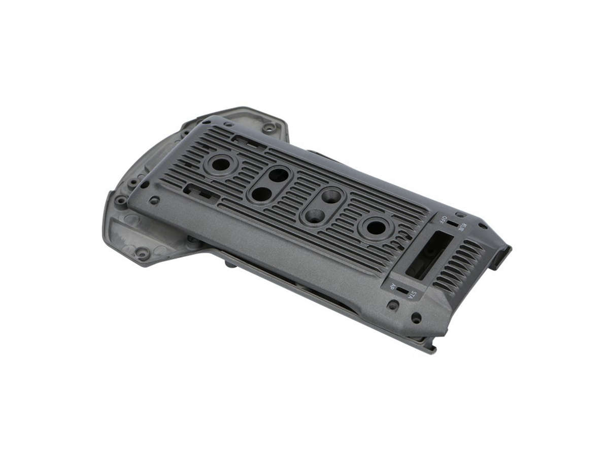
Bridge-tool casting | Process-like parts, pilot quantity, finish and assembly evidence | Full production-tool life, cavity balance, final production rate | Field test, launch bridge, or hard-tool release |
Production-tool trial | Final tool, alloy, process, cavity, trim, machining and finish interactions | Long-term capability until the process and measurement data are established | Tool correction, qualification, and production release |
Choose concept and fit prototypes
Use 3D printing for fast geometry learning
3D printing is useful when CAD geometry is still moving. It can expose interference, cable access, tool clearance, user handling, fastener access, and assembly order. Different printing processes and materials have different accuracy, surface, anisotropy, and temperature limits, so the chosen route must match the question.
Do not use a successful printed fit check as casting approval. Printed undercuts may be effortless while a die requires slides or machining. Thin printed ribs may not fill in metal. Flexible polymer clips do not predict a cast metal feature. Mark each finding as product geometry, prototype-process artifact, or casting DFM action.
Use urethane casting for appearance and small-batch learning
Urethane casting uses a master pattern and silicone mold to make plastic-like copies. It may suit appearance studies, assembly trials, user evaluation, seals, housings, or multiple design variants. Resin selection can approximate selected behaviors, but it does not become aluminum, zinc, or copper alloy.
Mold life and usable quantity depend on resin chemistry, heat, part size, draft, deep details, inserts, demolding stress, surface acceptance, and mold damage. Quote quantity per approved design and mold plan rather than assuming one standard output. If the design changes beyond trimming or simple local work, a new master or mold may be required.
Choose metal prototypes for function
A machined billet prototype can be the quickest path to a metal component when only a few parts are needed and castability is not yet the question. It can support assembly, thermal experiments, pressure-fixture development, and preliminary structural work. The designer should account for differences between wrought and cast material, including properties, internal structure, residual stress, and response to finish.
Machining the nominal final casting alloy may reduce the chemistry gap if suitable stock exists, but route differences remain. A die-cast grade may not be readily available as wrought billet in the required form. Even if chemistry matches, billet machining removes the casting skin and does not reproduce local solidification. Test reports must state material form and process so results are not transferred blindly.
Prototype castings can be made through routes such as sand or investment casting when geometry, alloy, size, and quantity fit. These parts can provide valuable information about cast-metal machining, heat treatment where applicable, coating, corrosion, and functional behavior. However, their cooling rate, section constraints, surface, and defect population may differ from pressure die casting.
Decide when the final alloy matters
Use the intended alloy when the decision depends on chemistry or material condition: corrosion exposure, coating response, thermal conductivity, machining behavior, joining, regulatory material approval, or representative mechanical testing. Identify the exact grade, standard, heat treatment, casting route, and specimen condition. “Production alloy” without these details is incomplete.
Using A380 aluminum in a non-die-cast prototype does not prove A380 pressure-die-cast performance. Likewise, a gravity-cast or machined zinc sample does not establish production behavior for Zamak 5 die casting. State which uncertainty the final alloy removes and which process uncertainties remain.
If the test only concerns package or handling, a substitute material may be faster and more economical. Requiring the final alloy for every early sample can delay learning without improving the decision. A fidelity matrix lets engineering and procurement pay for material realism only where it changes evidence.
Use bridge tooling for process-like parts
Bridge tooling sits between one-off prototypes and long-term production tooling. It may use a simplified cavity strategy, modular inserts, a lower-output tool material, or a tool designed for an interim quantity. The exact meaning of “soft tooling” varies, so the quote must identify tool material, process, cavities, slides, inserts, maintenance assumptions, included changes, and ownership.
Bridge tools can produce parts closer to the intended casting route and support machining, finish, assembly, field trials, packaging, supplier qualification, and launch inventory. They can also reveal gating, venting, ejection, flash, and thermal issues. However, simplified cooling, cavity count, automation, and tool material may differ from the production tool.
The bridge decision depends on quantity, design maturity, required process fidelity, launch timing, unit economics, and whether the tool can be modified. If the design is still moving rapidly, a bridge tool can become an expensive prototype. If the design is stable and pilot parts must resemble production, it may be the most informative step.
Plan precision from datums and measurement
A precise prototype must be precise in the features that support the decision. Establish datum intent, mating relationships, critical-to-quality characteristics, free or restrained measurement condition, and whether coating thickness is included. Do not apply production casting tolerances indiscriminately to a printed or urethane model; use the prototype process capability and the function being checked.
For machined prototypes, define stock, locating, fixture, and operation sequence. For cast prototypes, separate as-cast and machined dimensions. A coordinate measuring machine, scanner, comparator, gauge, or assembly fixture can be selected by geometry and purpose. Measurement reports should identify method, alignment, sample revision, and any deviations from the product drawing.
A prototype can intentionally use machined compensation to satisfy assembly while casting DFM continues. That is acceptable if the deviation is documented. It becomes risky when a manually adjusted sample is treated as evidence that the production process will hold the same result without the adjustment.
Plan machining and finish as part of the prototype
Precise cast components often reach final function through a combination of casting, machining, and finish. Prototype drawings should separate raw casting dimensions from machined requirements and identify the datum transfer between them. A functional bore, sealing land, thread, or bearing seat may need post-casting machining, while external walls remain representative of the chosen prototype route.
Machining a billet prototype can develop cutter access and assembly interfaces, but it may not expose the same subsurface discontinuities or stock variation as a production casting. Machining an alternate-route casting provides more relevant cast-metal experience, yet the final die-cast stock and locating behavior still require confirmation. Record fixture, tool sequence, stock, burr control, and any hand finishing.
Surface treatment trials need the proposed alloy and representative substrate when chemistry, casting skin, porosity, appearance, or adhesion matters. Powder coating adds film and cure heat; anodizing responds to alloy phases and cast/machined surface differences; plating and conversion treatments depend on cleaning and activation. Masking, racking, contact points, coating-sensitive dimensions, and visual standards should be included in the prototype scope.
Compare routes by cost of evidence
The cheapest individual part is not always the lowest-cost prototype plan. Include engineering preparation, pattern or tool, parts, secondary operations, inspection, testing, shipping, expected revisions, and the cost of a wrong decision. A low-cost model that cannot answer the required load or casting question adds a stage without retiring risk.
Conversely, production-like tooling can be premature while interfaces are changing. Estimate the expected value of information: what decision follows, how much investment it protects, and whether another route can answer it with acceptable confidence. This makes prototype purchasing comparable even when suppliers propose different processes.
For quantity, distinguish samples needed for fit, nondestructive measurements, destructive tests, finish variants, retained masters, customer approval, and spares. Reusing one part through several tests may save cost, but test order can change results. A validation matrix establishes how many accepted samples are genuinely required.
Verify casting-specific risks before release
Before permanent tooling, list uncertainties that substitute prototypes cannot close: fill through long thin paths, flow-front joins, trapped gas, local shrinkage, ejection distortion, parting-line mismatch, gate and overflow removal, and cavity-to-cavity variation. These belong to bridge or production-tool trials supported by casting simulation where warranted.
Inspection should target the predicted mechanism. Dimensional layout checks datum relationships and distortion. Radiography or computed tomography may investigate selected internal regions when geometry and resolution fit. Leak testing evaluates containment in the machined and assembled condition. Sectioning can answer a local development question. No single inspection proves all casting integrity.
Release evidence should identify sample revision, alloy, tool/cavity, process state, trim, machining, finish, measurement setup, and test condition. If a bridge tool differs from production in material, cavities, cooling, or manual operations, record which risks must be revalidated on the final tool.
Build a controlled iteration loop
Design changes are expected during prototyping, but revision control matters from the first build. Assign a unique model and drawing revision to each sample. Record why a change was made, what test or observation supports it, which interfaces it affects, and whether previous results remain valid. Retain a list of open casting DFM actions.
Use the cheapest route that can answer the next unresolved question. A printed insert may verify a connector move before a complete housing is remade. One machined sample may confirm fixture access before a pilot batch. A local tool insert may be replaceable in bridge tooling, while a change across the parting line can require extensive rework.
After every test, classify the result. Pass means the stated criterion was met for the tested sample and condition. Fail means the mechanism is understood enough to define a corrective action. Inconclusive means the fixture, measurement, sample variation, or prototype route prevented a decision. This prevents repeated builds that generate parts but not knowledge.
Schedule from dependencies
Prototype lead time is the sum of technical review, material procurement, model preparation, pattern or tool manufacture, casting or part build, heat treatment where applicable, machining, finishing, inspection, testing, and shipping. Some steps can overlap; others cannot begin until a revision or sample is approved. Calendar estimates should show these dependencies rather than one unsupported range.
The largest delays often come from incomplete inputs, late design changes, special material, complex cores or tool actions, fixture design, outsourced finish, and unclear acceptance. Freeze the revision for each build and identify long-lead items early. Decide whether partial delivery is useful, for example uncoated parts for dimensional review before finished samples complete environmental testing.
Fast-track work changes risk, not physics. Skipping DFM, measurement planning, or cure and test conditions may produce parts sooner but leave the next decision unresolved. A realistic schedule includes review and approval gates, plus a contingency for one evidence-driven iteration when the program risk warrants it.
Transfer learning to production tooling
Before production-tool release, consolidate prototype findings into the controlled product model, drawing, DFM record, material specification, machining plan, finish specification, and validation matrix. Close temporary deviations. A manually reamed hole, added shim, substitute resin, or nonproduction coating must not disappear from the handoff record.
Separate evidence that transfers directly from evidence that needs confirmation. Connector fit may transfer after geometry is frozen. A thermal trend from a metal prototype may guide design but need repetition on a production-intent casting. Coating adhesion on a sand casting may support chemistry selection while die-cast surface preparation still needs qualification. Production-tool trials close those remaining gaps.
Tool and die development should use the latest approved revision and explicitly incorporate gating, cooling, venting, ejection, parting, slides, machining stock, cosmetic limits, and critical zones. Prototype success is valuable only when its decisions survive this handoff.
RFQ inputs for a prototype program
Send the controlled 3D model and drawing, prototype purpose, required quantity, target material and acceptable substitutes, test and acceptance criteria, mating parts, critical dimensions, finish and appearance zones, machining needs, operating loads and environment, delivery priority, documentation, and expected production process and volume. Mark fixed features and areas open to DFM changes.
Ask the quotation to identify process, material form and condition, tool or pattern scope, expected fidelity and known differences from production, included inspections, sample sequence, revision cutoff, change cost, partial-delivery options, and assumptions. Lead time, usable quantity, tolerance, and price can then be confirmed for the reviewed scope.
A well-designed prototype program is not necessarily the one with the fewest stages. It is the one in which every stage retires a named risk before more money and schedule are committed. That discipline produces faster decisions and a cleaner route from an early model to a qualified precise casting.
Frequently Asked Questions