Zinc Die Casting a Watch Case Frame: 0.9 mm Lugs, Plating
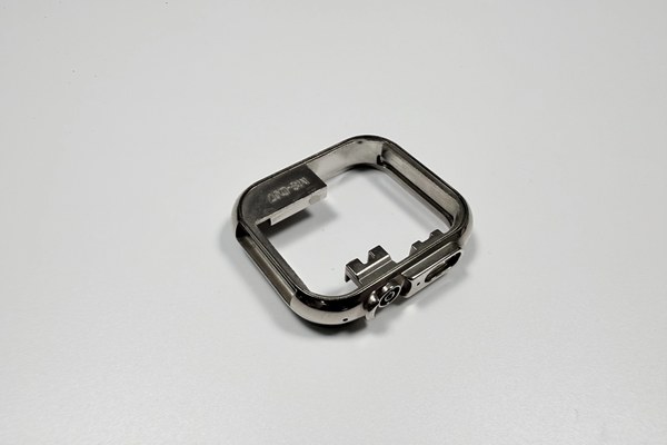
A 38.0×38.0×9.5 mm frame at 12±1 g carries four machined features. The bezel seat holds 0.03 mm step height, the movement cavity is 30.0 mm, the crown bore is Ø3.0 mm and the two lug bores Ø1.5 mm. Zinc die casting holds all four when the wall is cast first, the seat is milled after the polishing wheel and 18–27 µm of Cu/Ni/Cr lands last. Mill the seat first and 0.03 mm leaves the drawing.
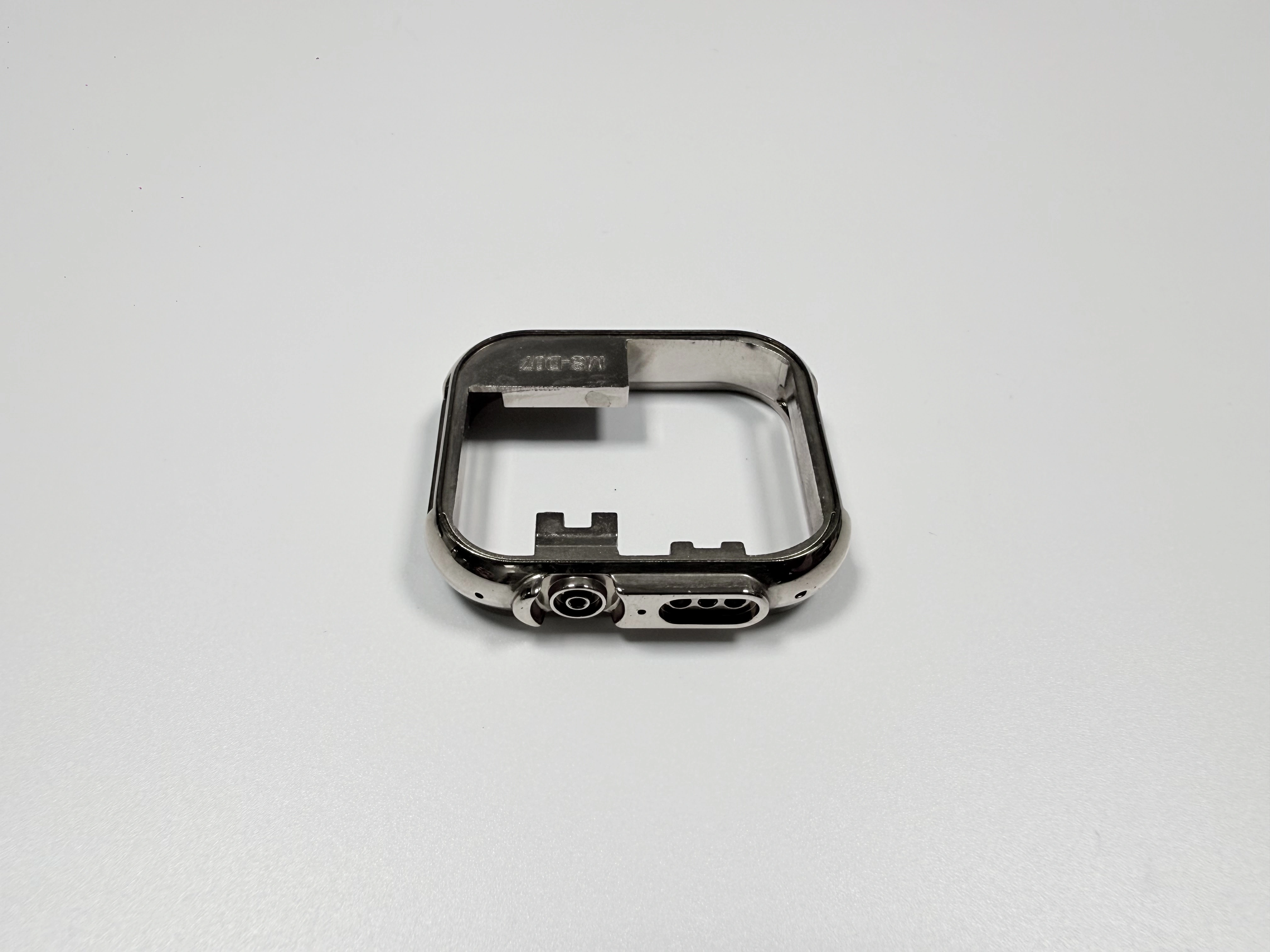
What four interfaces must a square watch case frame hold?
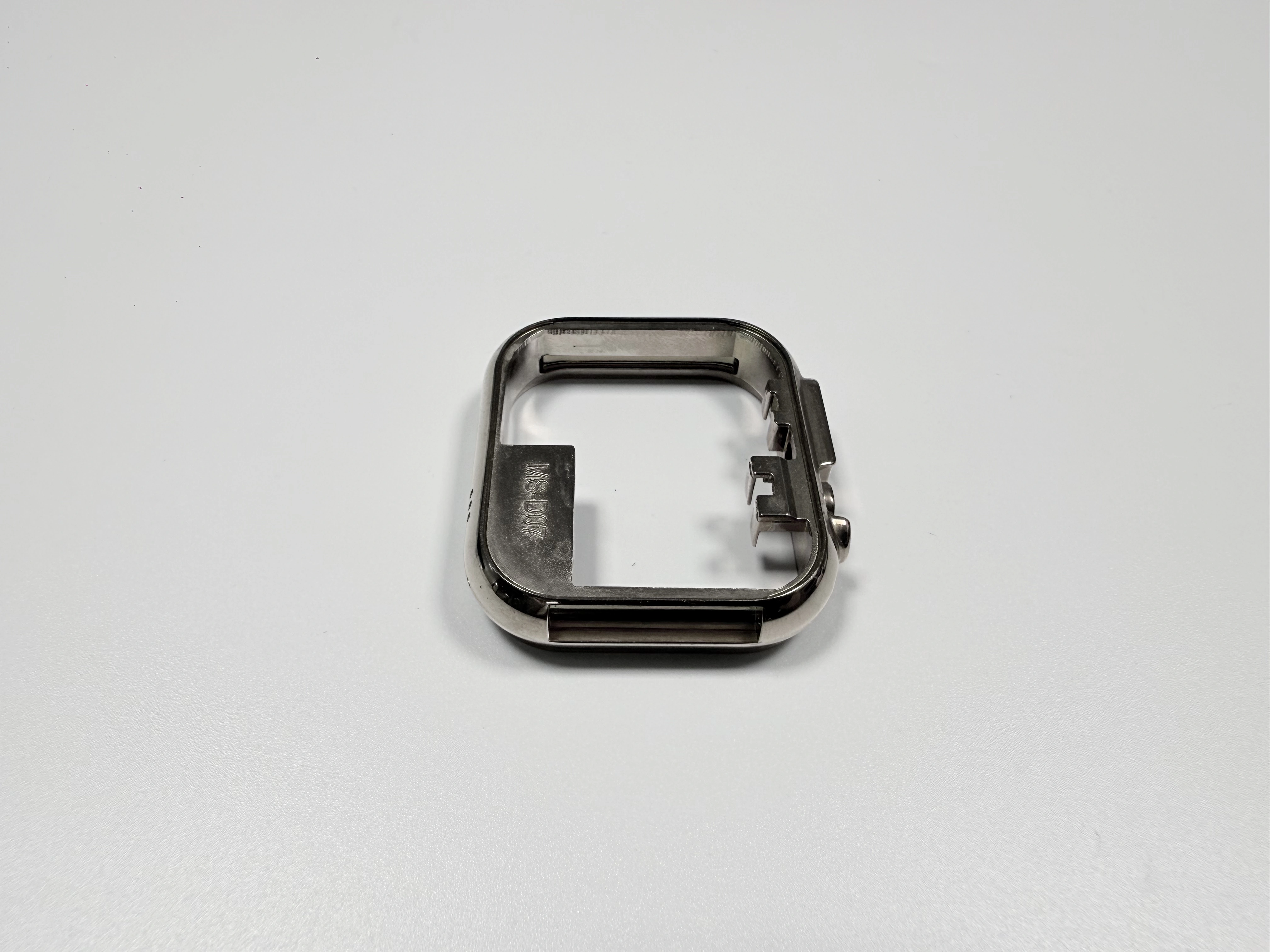
Four interfaces take four separate steps: the seat carries the mirror face and the cavity locates the movement. The cavity is 30.0 mm, upper deviation 0.05 mm, lower deviation 0; each lug bore is Ø1.5 mm, upper deviation 0.03 mm, lower deviation 0. Table 1 lists all four.
Interface | Target (mm) | Allowed band (mm) | Gauge |
|---|---|---|---|
Bezel seat height | 0.03 | 0–0.03 | Granite plate, feeler |
Movement cavity | 30.0 | 30.00–30.05 | Cavity plug gauge |
Crown bore | Ø3.0 | Ø3.00–Ø3.05 | Ø3.0 plug gauge |
Lug bores, two | Ø1.5 | Ø1.50–Ø1.53 | Ø1.5 plug gauge |
The lug wall sets the difficulty. It measures 0.9 mm at the thinnest point and 1.2 mm at the crown side, so a Ø1.5 mm bore is wider than the metal around it and the drill exits into open air. Three features are cut in one clamping; the fourth is drilled where nothing supports the exit.
Which machining steps does a 12 g frame replace?
The alloy is Zamak 5 to ASTM B86 AC41A, cast close to the 12±1 g finished weight. The route it displaces is a stainless block turned and milled to the same envelope: turning the outline, milling the cavity and the seat, then drilling the two lug bores and the crown hole. Four interfaces mean four tool paths and four setups; the casting forms the outline in one shot and leaves machining with only the four seats that carry tolerance.
Each interface above needs its own tool path on that block, so the machined route prices four setups against one shot here. Painted zinc is the third route on the same casting, cheaper at the start and softer at the edge. Because a plated edge is what a bezel rubs against, paint loses its price advantage once appearance enters the drawing.
Which dimensions does the case drawing list, plated or pre-plate?
Every tolerance on the frame needs a plated or pre-plate note. Copper, nickel and chrome add 18–27 µm per face, so a Ø1.5 mm lug bore closes by 0.036–0.054 mm across the diameter and the seat rises by the same amount. On a seat allowed 0.03 mm in total, that rise is the whole band.
Mark the seat, the crown bore and both lug bores pre-plate, and post-machining leaves plating stock where the deposit will land. Without that note, two tool shops quote one drawing to two finished sizes, and the gauge that passes one frame rejects the next.
Why must the gate sit at the thick lug wall?
A four-cavity die in 8407 steel, built to a 300,000-shot design target, feeds the thick lug walls at 12 and 6 o'clock. The thick wall freezes last, so pressure has to enter the cavity there and the gate has no other seat. The 0.9 mm section is last to fill and first to freeze, so overflow runs at 3 o'clock to both sides of the crown notch and drags the cold front past the thin edges.
Move the gate to the back face and the far lug fills last, so a cold shut (two metal fronts that met without welding) shows as a line the plating cannot close.
A four-cavity die costs more than a single-cavity tool, but the die cost is spread over the batch: total die cost divided by the number of frames, not by the number of cavities. On a 300-piece sample run it is divided by 300 frames. Before metal is counted, it is already the largest line in the price.
Where does the 400–420 °C melt lose heat in a 0.9 mm wall?
A melt at 400–420 °C loses its heat in the last millimetres of the 0.9 mm lug wall. A die face at 150–180 °C pulls it out faster than the next shot arrives, and specific pressure runs 20–30 MPa on a 25–35 s cycle. At this wall the gap between a short lug and a flashed split line is narrow.
The numbers are typical for the alloy, not settings for one machine; the first trial shots fix the window for this die. Trial shots produce machine hours rather than saleable parts, so a narrow window is a cost the sample order carries in full and a running order spreads across the batch.
Why does tumbling run before polishing and inspection?
Tumbling is the third of eleven steps, ahead of the polishing wheel and every gauge. Flash at the split line and a gate vestige beside the lug hide the wall condition, and ceramic media knocks the trimmed edge to a radius the wheel can follow.
Media lodges in the Ø1.5 mm bores, so a plug gauge clears each hole after the barrel rather than before it. Without that barrel the same flash comes off at a bench, one frame at a time, which puts hand labour into a chain otherwise carried by the shot.
Which three features must be cut after casting?
Three features are cut after casting: the 0.03 mm bezel seat, both Ø1.5 mm lug bores and the crown notch. CNC machining takes all three in one clamping, bores the crown hole at Ø3.0 mm and drills both lugs on one axis.
A chamfer goes in before the drill point touches metal, and the feed drops through the break-out. One example record lists nine chipped lug exits in 300 pieces; those nine were scrapped, and the chamfer plus the lower feed took the next lot to zero. A chipped exit is scrap rather than rework, because blending takes the bore oversize.
Why must the 0.03 mm seat be milled rather than polished?
Milling runs after the wheel, because a polishing wheel cuts hardest where it bears and leaves no measurable flat. Table 2 sets the two orders side by side; only one leaves a step a feeler can confirm.
Order | Holds? | Adds |
|---|---|---|
Polish, then mill | Yes, 0.03 mm step set at milling | One extra clamping |
Mill, then polish | No, the polished step moves | Re-cut, re-check |
The two orders differ by one clamping, and that clamping is the price difference: a second fixture position, a second datum and a second in-process check, charged on every frame. A seat over 0.03 mm after the milling pass is scrapped, because a second pass cuts the whole face rather than the high spot.
Which three plating layers does the X-ray gauge measure?
The release check confirms three layers per face: copper at 8–12 µm, nickel at 10–15 µm and chromium at 0.1–0.3 µm, 18–27 µm in total. An X-ray coating gauge reads each layer on its own, and the nickel layer carries the corrosion barrier under the chromium wear face.
Blisters start in a pore, where acid from the copper stage stays and expands under a sealed nickel film. Porosity belongs to the die and the shot, so the plating spec and the casting spec travel as one document. Three layers mean three passes through a bath, and rack density sets how many frames ride each pass; a 12 g frame with a 0.9 mm wall fills a rack badly. Surface finishing covers the options around that rack.
Which eight checks release a plated frame?
Eight checks release the frame, three of them coating tests, and each answers a failure the others cannot see. Table 3 lists the tests, from a heat-shock oven to a salt-spray chamber.
Test | Standard | Limit |
|---|---|---|
Heat shock | ASTM B571 | 200 °C, 1 h, no blister |
Salt spray | ASTM B117 | 240 h, no base metal corrosion |
CASS | ASTM B368 | 48 h, grade 9 or better |
The eight run from a Ø1.5 mm plug gauge on each lug bore and a granite plate with a 0.03 mm feeler to a cavity plug gauge, a vision system or CMM, the X-ray coating gauge, a heat-shock oven, a salt-spray chamber and a D65 light box. Drop one and a failure mode goes unseen.
The 240 h salt spray sets the lead time as much as the acceptance. A salt-spray chamber holds a frame for ten days, so the first frame in on day one sets the earliest ship date, and no expedited rack shortens the soak.
What rules out cast-and-plate for a case frame?
Cast and plate fails on three duties: a wall below 0.9 mm, a diving rating, and any face that takes sustained abrasion. A plated Zamak frame meets sweat, friction and daily knocks; it is not a dive case, and no coating in the 18–27 µm range changes that.
Stainless machined from solid wears better and weighs more, so a drawing that asks for 0.03 mm on a wall under 0.9 mm has picked the other route already. Anything thinner fails in the shot, after the die is paid for, and no polishing pass brings it back. A CNC fit case records the same rule on a Zamak part.
What makes up the quote for a cast and plated frame?
Five lines build the quote for a 12 g frame. One clamping covers the three machined features, two polishing passes cover the visible faces, and the rest is rack density in plating, the scrap allowance a thin wall carries and the die spread across the batch.
Four inputs fix those lines: a 2D drawing with a plated or pre-plate callout on every tolerance, a 3D model, the batch size and the surface grade on the visible faces. Missing one turns the answer into a range no second quote can be compared against. Send all four with the drawing, and check the seat and both lug bores on the first article.
FAQ