Aluminum Die Cast Motor Housing Design: Alignment, Thermal Paths and Production Validation
Aluminum die cast motor housing design must connect the rotor, stator, bearings, end covers, mounting system, connector interfaces and thermal path. A cylindrical casting is not automatically a functional motor housing. The final part may need a controlled stator interface, coaxial bearing-seat-type features, end-cover registers, mounting feet, fins, grounding pads and masked machined surfaces.
These functions compete. A thin wall reduces mass but can distort under casting, machining, stator insertion or bolting. Heavy ribs and connector bosses increase stiffness locally but can create uneven sections and shift roundness. Coating can protect the exterior while insulating a required electrical or thermal contact. Buyers need a release plan that follows the complete assembly stack.
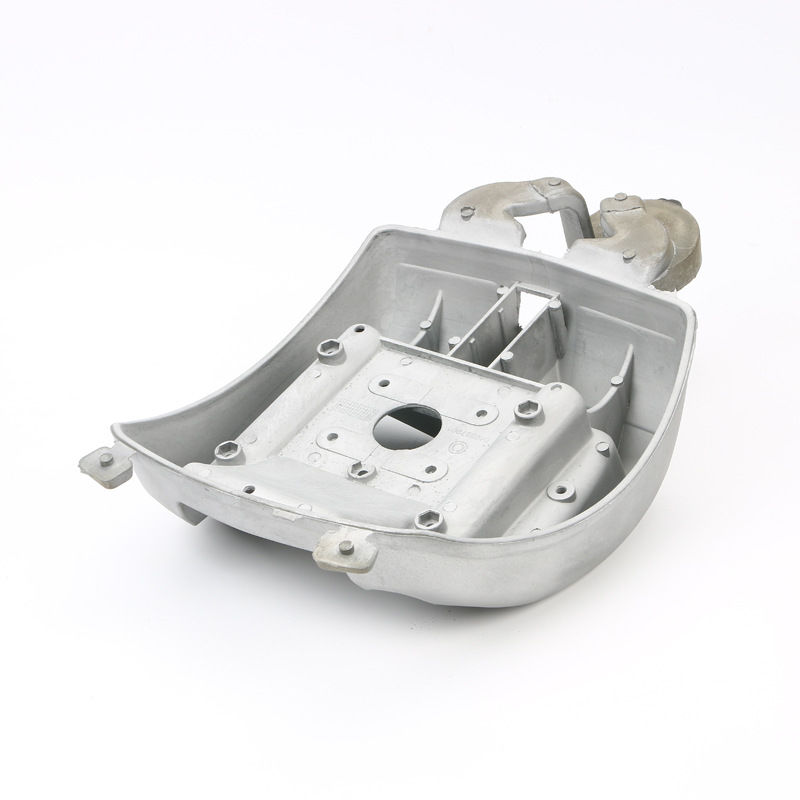
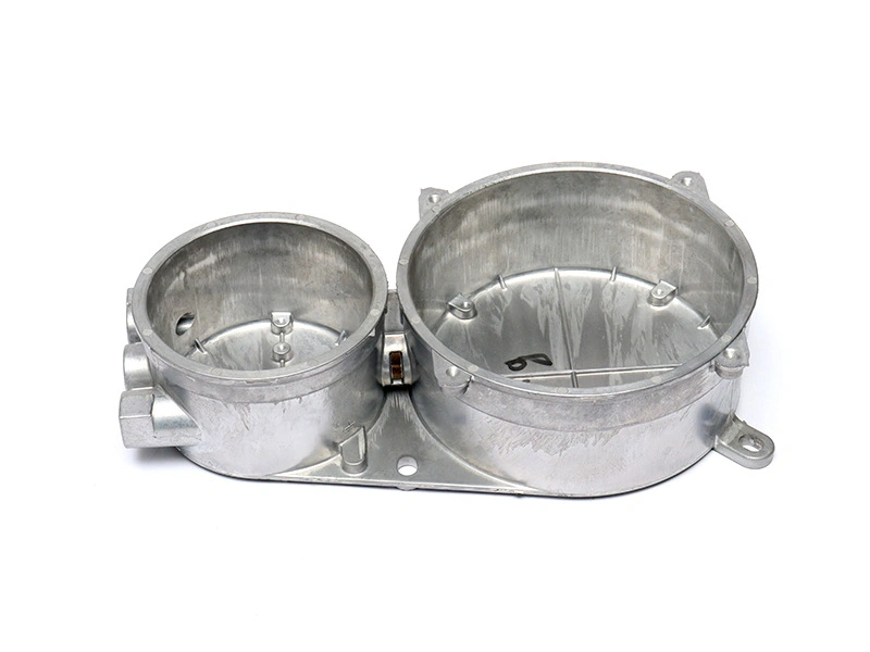
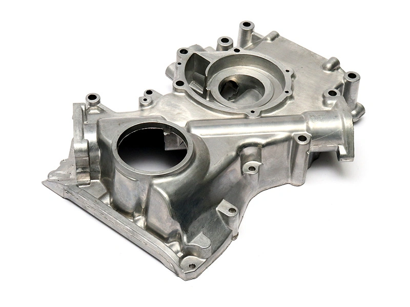
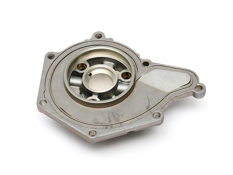
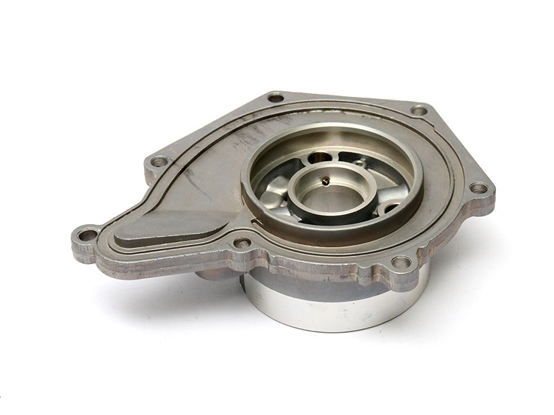
The images show a circular aluminum cast enclosure from internal and external views. They support discussion of motor-housing-type geometry only. They do not establish actual end use, material grade, coaxiality, heat transfer, vibration or service performance.
Which Motor-System Inputs Should Be Defined Before Housing DFM?
Begin with stator and rotor envelopes, bearing and shaft relationships, end-cover architecture, mounting orientation, torque reactions, vibration, speed, temperature range, heat sources, cooling route, connector loads, sealing, grounding and finish requirements. State assembly sequence and serviceability. The product team owns these inputs; the casting supplier translates them into manufacturable features.
Separate component dimensions from functional relationships. A stator interface may need controlled size, roundness and texture. Bearing-seat-type features may need a common axis with an end-cover register. Mounting feet may establish the product datum while a flange controls end-cover position. Define which characteristics matter in free state and which matter only after bolting or stator installation.
System Input | Housing Decision | Evidence Source |
|---|---|---|
Rotor/stator stack | Internal envelope and air-gap-related datums | Motor design |
Bearing/end-cover architecture | Seat, register and common-axis controls | Bearing and assembly design |
Heat generation/cooling | Thermal contact, wall and fin route | Thermal analysis/test |
Mounting loads | Feet, flange and rib load paths | Structural requirement |
Electrical grounding | Bare contact and coating masks | Electrical safety/design |
Environment/finish | Alloy, pretreatment, coating and sealing | Product environment specification |
A useful structural and thermal analysis combines realistic interfaces and loads. Datasheet conductivity or a generic simulation does not establish assembled motor temperature.
How to Build a Functional Datum Chain for the Cylindrical Housing
Choose datums from assembly function. A mounting face or feet may establish the primary plane, an end-cover pilot or stator interface can establish lateral position, and a pin or bolt feature can control clocking. Bearing seats and end-cover registers should be related through a clear datum reference frame instead of independent coordinate origins.
When bearings are located in opposite covers, the housing registers that position those covers can control the final shaft axis even if the housing has no direct bearing bore. When one seat is machined in the housing and another in a cover, the register, face and bolt pattern transfer alignment. Review the complete chain through mating components.
Feature | Functional Role | Control Question |
|---|---|---|
Mounting face/feet | Installs motor in equipment | Does clamping distort the cylinder? |
Stator interface | Locates and supports stator | How are size, form and thermal fit defined? |
End-cover register | Locates bearing-carrying cover | Is the register coaxial to the intended axis? |
Bearing-seat-type bore | Supports bearing or shaft system | Are form and alignment controlled together? |
Clocking feature | Orients connector and covers | Is rotation controlled without overconstraint? |
A vague concentricity note can hide the intended relationship. Use the applicable drawing standard to control size, form, position, orientation and runout from functional datums. The inspection plan should reproduce the same frame.
How Wall Thickness, Ribs, Fins and Bosses Change Fill and Roundness
Cylindrical walls benefit from consistent sections, but motor housings often include feet, flange rings, fins, terminal-box bosses and bolt towers. These features create asymmetric stiffness and cooling. A heavy foot can pull one side of the cylinder, while a dense fin root can alter fill and local heat flow. A connector boss can interrupt the circular support around a stator interface.
Use ribs to transfer defined loads rather than adding continuous thick material. Blend roots, avoid unnecessary cross-intersections and maintain draft and ejection access. Fin thickness, spacing and height must be feasible for fill and tool release; more fins do not automatically produce better system cooling if contact and airflow are weak.
Geometry | Potential Benefit | Manufacturing Risk |
|---|---|---|
Uniform cylindrical wall | Balanced structure and thermal path | Thin-fill and ejection limits |
External fins | Increase external area | Incomplete fill, damage and thick roots |
Mounting-foot ribs | Carry installation loads | Local mass and cylinder distortion |
Connector boss | Supports electrical interface | Hot spot and interrupted wall stiffness |
Heavy end flange | Supports cover and fasteners | Cooling imbalance and face warpage |
Die casting mold-flow analysis can compare filling, venting and thermal concentration around fins, bosses and flange rings. Correlate predictions with short-shot, trial, dimensional and internal-quality evidence before production release.
How Stator Fit and Thermal Expansion Should Be Translated Into Controls
Define how the stator is located and retained: interference, transition or clearance fit, bonding, shoulders, fasteners or another approved method. The stack includes stator outside limits, final housing size and form, surface condition, material expansion, operating temperatures, insertion method and housing stiffness. No universal bore tolerance is appropriate for every motor.
Aluminum generally expands more than steel, but actual stator and housing temperatures, gradients and constraints control the working fit. A room-temperature interference can reduce in service or become difficult during cold assembly. Excess interference can distort laminations or the housing; insufficient retention can allow movement. Product engineering should assess both extremes and validate assembly.
Fit Contributor | Question | Validation |
|---|---|---|
Stator outside size/form | What is the true mating envelope? | Supplier data and incoming measurement |
Housing bore/interface | Are diameter, roundness and taper controlled? | Multi-depth/direction inspection |
Assembly temperature | What fit and force exist during installation? | Temperature and force/displacement record |
Operating temperature | Does retention remain at extremes? | Thermal and functional correlation |
Housing asymmetry | Does the interface ovalize near feet/bosses? | Circumferential form and assembly check |
Coating and adhesive thickness belong in the final stack where they enter the interface. Do not use an uncontrolled paint film to repair an oversize stator bore. If bonding is designed, specify gap, cleanliness, cure and temperature compatibility.
How Machining Stock, Fixtures and Sequence Protect Alignment
Machining stock must clean cast variation while preserving wall around the stator and bearing interfaces. Map cast cylinders and registers by cavity before defining stock. Deep one-sided cuts can change wall stiffness and expose porosity. Operation one should create a stable face, pilot and clocking reference tied to the assembly frame.
The fixture should support stiff pads without forcing the cylinder round. Clamps across a thin wall can machine a good restrained diameter that springs into lobing after release. Measure clamp displacement and compare in-fixture and free-state form during development. A long boring bar or interrupted fin/flange geometry may require staged roughing and finishing.
Machining Element | Control | Failure if Weak |
|---|---|---|
First-operation datum | Functional face/pilot/clock relation | Aligned features in wrong assembly frame |
Stock distribution | Cavity and circumferential map | Incomplete cleanup or thin wall |
Clamp reaction | Supported minimum-force path | Free-state roundness loss |
Tool reach | Bar stiffness and chip evacuation | Taper, chatter or axis drift |
Temperature | Warm-up, coolant and gauge condition | Size trend across production |
The post-machining route should link program, fixture, tool, cavity and inspection identity. Changing a cutter or support near a bearing or stator interface is a functional change, not only a cycle-time adjustment.
How Thermal Paths and Contact Surfaces Should Be Defined
Trace heat from windings and stator through contact interfaces, housing wall, fins, mounting interfaces and surrounding air or coolant system. Contact pressure, interface material, surface condition and coverage can dominate a thermal path. Nominal aluminum conductivity does not describe an assembled interface with gaps, coating or uneven fit.
Separate surfaces intended to transfer heat from purely cosmetic exterior faces. A machined thermal pad may need controlled flatness and texture; a stator interface may need known contact; fins need airflow and unobstructed roots. Model assumptions should include realistic contact resistance, loads and boundary temperatures, then be correlated with physical tests specified by the product owner.
Finite element analysis can compare stiffness, thermal expansion and contact effects, but mesh, material state and boundary conditions must be documented. It cannot certify temperature rise from geometry alone.
Which Surfaces Should Be Masked for Grounding, Fit or Thermal Contact?
Create a mask map before coating. Candidate bare zones include grounding pads, threaded electrical contacts, stator or bearing interfaces, end-cover pilots, gasket lands and machined thermal contacts. Whether each surface remains bare depends on corrosion, electrical, thermal and assembly requirements. Bare aluminum may need controlled protection or assembly timing.
Define the coating transition relative to functional edges. Overspray or edge buildup can change a register or prevent metal-to-metal contact, while excessive mask retreat can expose cosmetic or corrosion-sensitive area. Inspect masks after removal for residue, lifted edges and contamination.
Surface | Reason to Mask | Release Check |
|---|---|---|
Grounding pad | Maintain designed electrical contact | Location, cleanliness and specified resistance test |
Thermal pad | Avoid insulating film in contact path | Flatness, texture and clean transition |
Register/bore | Protect fit and location | Final gauge after mask removal |
Seal land | Preserve designed seal interface | No residue, damage or edge ridge |
Thread | Maintain engagement and contact | Plug removal and thread gauge |
Where powder coating is selected, the powder coating process must be qualified with the casting pretreatment, cure exposure, mask design and final dimensional checks. This article does not choose the finish system for the buyer.
How Free-State, Assembly and Performance Evidence Should Connect
First inspect the free casting and machined housing in the released datum frame. Then measure the states created by stator insertion, end-cover bolting and mounting, where required. Assembly can change roundness, register position and bearing alignment. Use production-intent components and controlled torque, temperature and sequence.
CMM dimensional inspection can evaluate axes, registers, feet and planes when point strategy and restraint are controlled. Correlate geometric data with assembly runout, insertion force, vibration, noise and temperature-rise tests defined by motor engineering. A CMM pass cannot prove motor performance, and a quiet prototype cannot replace dimensional control.
Release Layer | Evidence | Purpose |
|---|---|---|
Cast state | Stock, wall, fill and cavity variation | Protect machining and structure |
Machined free state | Size, form, axis, datums and surfaces | Confirm drawing compliance |
Subassembly state | Stator/end-cover effect and runout | Confirm assembly stack |
Functional state | Product-defined thermal/vibration/noise data | Validate system behavior |
Pilot production | Cavity, fixture and tool-life variation | Confirm repeatability |
Hypothetical Circular Motor-Housing Release Scenario
Consider a hypothetical cylindrical casting with an internal stator-type interface, an end-cover register, a bearing-bore-type opening, external mounting pads and a connector boss. The geometry resembles the design questions visible in the images, but the images are not a motor-housing case study.
The team defines the mounting plane and cover register as the functional frame, maps the stator and bearing relationships, and identifies a thick transition where the connector boss meets the cylinder. The boss and ribs are revised after fill and structural review. Machining establishes the mounting and register datums before finishing internal interfaces. Clamp displacement is checked to prevent forced-round machining.
A mask map keeps the pilot, stator interface, grounding pad and thermal contact in their approved final condition. Serialized pilot parts are checked before and after stator/end-cover assembly, then correlated with the product-defined thermal and vibration tests. No performance outcome is assumed.
Gate | Output | Hold Condition |
|---|---|---|
System definition | Functional stack and boundary conditions | Unowned fit or thermal assumption |
DFM/tooling | Section, fill, slide and ejection review | Unstable fin/boss or inaccessible feature |
Machining trial | Datum, stock and free-state form | Clamp springback or axis disagreement |
Assembly trial | Fit, runout and interface condition | Unexplained insertion or alignment shift |
Pilot release | Functional correlation and traceability | One sample without variation evidence |
What to Include in an Aluminum Motor-Housing RFQ
Provide controlled 3D and 2D data, stator and end-cover interfaces, bearing information, mounting loads, fit ownership, assembly temperatures and sequence, thermal boundary conditions, grounding requirements, environmental finish, quantity, life, inspection and functional validation. Mark CTQs and distinguish supplier manufacturability input from product-design approval.
Request a DFM response covering wall/rib/fin sections, connector bosses, gate/vent/cooling strategy, machining stock, first-operation datums, clamp reaction, tool access, mask map, CMM strategy and change controls. Do not accept a quote that assumes every circular face can be machined independently.
RFQ Item | Buyer Defines | Supplier Returns |
|---|---|---|
Functional stack | Stator, rotor, bearing, cover and mount | Datum and process assumptions |
Thermal route | Heat sources and boundary conditions | Geometry/contact manufacturability |
Casting | Material/performance and zones | Fill, vent, section and tooling concept |
Machining | Final geometry and assembly frame | Stock, fixture and gauge plan |
Finish | Environment, color and bare surfaces | Pretreatment, mask and final checks |
Release | Reports and functional tests | First-article/pilot evidence matrix |
A controlled motor-housing-type casting is not released by appearance or one diameter. It is released when the assembly datums, fits, thermal contacts, coating boundaries and product-defined functional results remain connected through representative production parts.
How Change Control Preserves Motor-Housing Performance
Review changes to alloy condition, die inserts, gates, vents, cooling, fin or rib geometry, stock, first-operation targets, fixtures, cutters, stator or bearing supplier, adhesive, coating, masks and assembly temperature. Link each change to the dimensions, interfaces and performance evidence it can affect.
Retain approved free-state and assembled-state reports, boundary samples where useful, tool and fixture revisions, coating records and product-test correlation. Trend data by cavity and fixture position. An average can hide one cavity that produces an oval stator interface or one fixture nest that tilts a register.
When a vibration, temperature or assembly complaint occurs, preserve the as-found housing and mating components. Compare geometry, contact marks, fit, coating boundaries and process identity before rework. The investigation should separate motor-system causes from housing variation rather than assuming the casting is responsible.
How to Build an Alignment and Interface Error Budget
List every contributor between the mounting frame and the rotating system: housing face orientation, register axis, cover fit, bearing-seat position, stator-interface form, cover-face runout, fastener clearance and assembly deformation. Convert angular errors into positional effect over the relevant span. Independent tolerances can each pass while their worst-direction combination consumes the functional allowance.
Separate manufacturing contributors from mating-component and assembly contributors. Use worst-case analysis where failure consequence requires it, and use statistical assumptions only after stable distributions and independence are demonstrated. Reserve measurement uncertainty rather than treating inspection as exact.
Budget Contributor | Control Evidence | Review Trigger |
|---|---|---|
Housing register axis | Datum-based CMM data | Tool, fixture or stock change |
Cover pilot clearance | Boundary component stack | Cover supplier or tolerance change |
Bearing-seat axis | Form and alignment measurement | Machining-route change |
Assembly distortion | Free versus bolted comparison | Fastener, torque or mounting change |
Review the budget against production-intent assemblies and functional data. The purpose is not to distribute the same tolerance equally; it is to allocate control where process capability and function justify it.
FAQ
How Should Motor-Housing Bearing Seats and End-Cover Registers Share Datums?
How Do Wall Thickness and Rib Layout Affect Motor-Housing Roundness?
Which Motor-Housing Surfaces Should Stay Bare for Grounding or Thermal Contact?
How Should Stator-Fit Requirements Be Converted Into Casting and Machining Controls?
What Evidence Should Revalidate a Motor Housing After an Alloy or Tooling Change?