Painting Die Cast Aluminum Parts: Preparation, Film Build and Finished-Part Approval
Painting die cast aluminum parts requires control of the entire surface system, not only the final color. Oil, release residue, oxide, blasting media, machining coolant, fingerprints and trapped contamination can weaken adhesion. Primer and topcoat must be compatible with the aluminum condition, environment, appearance, cure exposure and assembly.
Complex housings add geometric risk. Paint can build on edges, remain thin at sharp transitions, run on vertical walls, bridge a mask, collect in recesses or enter threads and sealing faces. A sample sprayed carefully by an experienced operator does not establish production repeatability. Buyers should specify both cosmetic and functional acceptance.
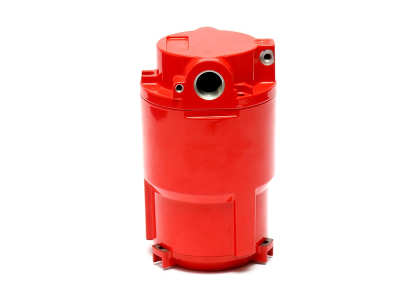
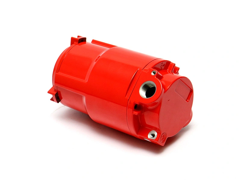
The images show a red painted circular cast housing from two directions. They support discussion of coverage, openings and appearance only. They do not identify the alloy, paint chemistry, primer, film build, cure, adhesion or corrosion-test result.
Which Inputs Define a Paint System for Die Cast Aluminum?
Define the service environment, indoor or outdoor exposure, chemicals, temperature, UV, abrasion, required life, appearance, color, gloss, texture, touch points, allowable defects, electrical or thermal contacts, sealing interfaces and packaging. State substrate alloy and condition where known, previous operations, quantity, repair policy and applicable customer or industry standards.
The paint supplier and finisher should propose a qualified preparation, pretreatment, primer and topcoat system for those inputs. One-component and two-component coatings, solvent- or waterborne routes and different resin families have different application and cure behavior. This article does not prescribe a chemistry or corrosion duration.
Buyer Input | Paint-System Decision | Release Evidence |
|---|---|---|
Environment | Pretreatment, primer and topcoat family | Specified qualification test |
Color/gloss/texture | Pigment, application and appearance window | Approved master and controlled lighting |
Wear/handling | Film toughness and protected zones | Product-specific test/handling trial |
Geometry | Spray access, orientation and mask design | Coverage map and boundary parts |
Assembly interfaces | Coated, controlled-film or masked condition | Final gauges and functional assembly |
Packaging | Cure-to-pack time and separators | Transport/rub challenge |
The painting service overview provides general process context. A production specification still needs project-specific substrate, system, film and acceptance details.
How Casting and Machining Condition Affect Paint Readiness
Die cast surfaces can carry release residues, oxidation, embedded contamination and locally different texture. Machined faces can retain coolant and fine chips. Porosity may release trapped cleaner or air during heating, creating pinholes or blisters. Burrs, sharp edges, dents and ejector marks remain visible through paint rather than disappearing.
Define incoming acceptance before pretreatment: no incompatible oil, silicone or marker; controlled burrs and flash; agreed surface defect limits; dry internal cavities; and protected functional faces. Keep cast and machined parts separated from dirty handling after cleaning. Gloves and clean racks matter because fingerprints can become local adhesion failures.
Substrate Condition | Paint Risk | Control |
|---|---|---|
Release agent or oil | Crater, fisheye or weak adhesion | Qualified cleaning and water-break/other check |
Oxide/corrosion | Unstable interface | Controlled oxide removal/pretreatment |
Machining coolant | Residue in pores, threads or edges | Post-machining wash and dry |
Porosity/outgassing | Pinholes, bubbles or blisters | Risk trial and compatible process window |
Sharp edge/burr | Thin film or visible defect | Defined edge preparation before paint |
Aluminum die casting quality and paint quality should be reviewed together. Painting cannot make a dimensionally wrong, contaminated or structurally unacceptable casting conform.
How Cleaning, Deoxidizing, Conversion and Primer Work Together
Cleaning removes oil and particulate. Deoxidizing or etching, when specified, controls the oxide and surface condition. A conversion treatment can improve paint adhesion and corrosion behavior when compatible with alloy and system. Primer promotes adhesion, barrier performance, color holdout or other functions. Each stage needs concentration or bath condition, time, temperature, rinse and contamination control according to the approved process.
Primer is not automatically required or optional. Some direct-to-metal systems are qualified without a separate primer for defined environments, while demanding exposure or substrate conditions may require one. Compare the complete tested system. Skipping primer because a sample looks good can sacrifice durability; adding primer without controlling total film can affect fit and cure.
Layer/Stage | Main Function | Failure if Uncontrolled |
|---|---|---|
Degreasing | Remove oils and release residue | Fisheyes and adhesion loss |
Oxide control | Create consistent active surface | Variable bonding |
Conversion as specified | Support adhesion/corrosion system | Underfilm corrosion or weak interface |
Primer | Bond/barrier/holdout as designed | Delamination or color variation |
Topcoat | Color, appearance and environmental surface | Fade, wear or cosmetic rejection |
Test adhesion on the final production sequence, not on laboratory-clean flat coupons alone. Coupons help monitor chemistry, while cast parts expose recess, edge, outgassing and mask effects.
How Wet Film Becomes Dry Film and Why Solids Matter
Wet-film thickness is measured soon after application and helps the operator control deposition before cure. Dry-film thickness is the remaining film after solvent or water release and cure. The relationship depends on coating solids, application transfer, thinning within the approved process, substrate shape and cure. Use the coating supplier's validated data rather than a generic conversion.
Measure wet film at accessible representative zones where the method is suitable. Curved cast surfaces and small features can make comb-gauge readings unreliable. Dry-film instruments need calibration and substrate correction for aluminum geometry, roughness and curvature. Destructive cross-sections may be used during qualification when non-destructive access is weak.
Film Variable | Why It Changes | Control |
|---|---|---|
Wet film | Gun setting, speed, distance and overlap | Qualified map and in-process checks |
Dry film | Solids, flash and cure | Final calibrated measurement |
Edge film | Surface tension and geometry | Edge preparation and targeted validation |
Recess film | Spray angle and air movement | Part orientation and access study |
Mask-edge buildup | Spray overlap and removal timing | Transition standard and final gauge |
More film is not always better. Excess thickness can run, trap solvent, crack, change color or interfere with assembly. Too little film can reduce coverage and protection. Specify a system window based on qualification.
How Flash-Off and Cure Should Be Controlled
Flash-off allows volatile components to leave between coats or before cure. Insufficient flash can promote solvent popping, sagging or trapped volatiles; excessive delay can exceed the recoat window and weaken intercoat adhesion. Follow the coating supplier's approved time, temperature, airflow and humidity window.
Cure depends on actual part temperature and time, not oven display alone. Thick cast sections heat and cool differently from thin coupons. Map representative part temperatures during qualification and control rack loading, oven zones and line stops. Confirm that plugs, seals or inserted materials tolerate the cycle.
Process Signal | Possible Failure | Evidence |
|---|---|---|
Short flash | Runs, solvent pop or trapped volatiles | Time/environment record and defect map |
Long recoat delay | Intercoat adhesion loss | Recoat-window traceability |
Under-cure | Soft film, print or weak resistance | Part-temperature/cure verification |
Excess heat | Color shift, film or component damage | Upper-bound part profile |
Early packing | Blocking, imprint or rub | Cure-to-pack validation |
Why Complex Housings Get Runs, Thin Edges and Overspray
Runs and sags occur when wet paint cannot hold on a vertical or lower surface before flash. Thin edges arise because film pulls away or spray access is poor. Overspray can dry before reaching the part, creating rough texture, or enter an opening that should remain clean. Deep recesses and internal corners can collect excess film or receive too little.
Control part orientation, gun path, atomization within the qualified coating process, distance, overlap, line speed, flash and viscosity according to supplier instructions. Operators should not solve one thin area by flooding the entire housing. Build a coverage map with high-risk edges, recesses, underside zones and mask transitions.
Mechanical preparation may be part of the route. Sand blasting for cast parts requires controlled media, cleanliness and surface profile and does not replace degreasing or chemical pretreatment. Mask sealing and precision surfaces before blasting when required.
How Threads, Seal Lands, Grounding Points and Bores Are Masked
Create a drawing-based mask map that labels no-paint zones, controlled-film zones and full-coverage zones. Define the transition tolerance and final state after plug or tape removal. Threads, registers, bearing/stator interfaces, gasket lands and grounding pads often need masking, but the product specification decides each one.
Plugs must fit without damaging threads and survive pretreatment, spray and cure. Tape or liquid masks must not leave adhesive or contaminate the coating. Remove masks at the qualified stage to avoid tearing or creating a high ridge. Reinspect critical dimensions after removal.
Mask Zone | Why Controlled | Final Check |
|---|---|---|
Thread | Engagement and cleanliness | Visual, residue and thread gauge |
Sealing land/groove | Seal surface and geometry | No paint ridge, residue or damage |
Register/bore | Dimensional fit | Final variable/functional gauge |
Grounding pad | Electrical contact | Clean area and specified assembly test |
Interior cavity | Fluid, debris or assembly requirement | Coverage/exclusion and cleanliness check |
How Color, Gloss, Texture, Adhesion and Film Are Approved
Approve color and gloss against a controlled master under defined lighting, viewing angle and distance. Instrumental color data can improve repeatability, but limits must be agreed for the actual paint and geometry. Curvature and texture change visual appearance. Separate critical cosmetic zones from hidden or functional zones.
Film thickness should be mapped at representative flats, curves, edges and recesses with a qualified instrument. Adhesion methods damage the coating and require defined sample locations or witness panels where appropriate. Qualification can include product-specific corrosion, chemical, impact, abrasion or weathering tests, but no one test guarantees service life.
Acceptance | Method Direction | Risk if Vague |
|---|---|---|
Color | Master and/or agreed instrumental method | Lighting-based disputes |
Gloss | Specified geometry and measurement angle | Curved-part mismatch |
Texture/orange peel | Visual master or quantified method | Subjective rejection |
Dry film | Calibrated zone map | Hidden thin or overbuilt regions |
Adhesion | Approved destructive method/location | Unrepresentative coupon pass |
Decorative coating planning should distinguish appearance from protective and functional requirements. A beautiful sample can still fail masking, fit or adhesion.
How to Diagnose Common Paint Defects Before Rework
Preserve the defect and record location, orientation, batch, operator or robot program, material lot, mix time, viscosity or approved process checks, flash, cure and substrate history. Fisheyes suggest contamination but can also involve spray-air or equipment sources. Pinholes can involve outgassing, trapped volatiles or substrate condition. Runs indicate local wet-film and flash behavior.
Do not sand and respray before identifying whether the defect reaches primer or substrate. Rework compatibility, surface preparation, recoat window and total film must be approved. Repeated cosmetic repair can create excessive thickness, color mismatch or weak interfaces.
Defect | Competing Causes | Evidence |
|---|---|---|
Fisheye/crater | Oil, silicone, air or equipment contamination | Cleanliness and source map |
Pinholes | Porosity outgassing or solvent release | Substrate, flash and cure comparison |
Run/sag | High wet film, orientation or short flash | Film map and process record |
Dry spray/roughness | Distance, atomization, overspray or airflow | Gun path and zone pattern |
Peeling | Contamination, pretreatment or intercoat failure | Failure interface and retained process data |
For corrosion-focused systems, anti-corrosion coating principles can guide failure questions. Product approval still depends on the specified test and service environment.
Hypothetical Red Cylindrical Housing Release Scenario
Consider a hypothetical red cylindrical die cast housing with an open bore, mounting holes, external walls and interior transitions. The images illustrate these visible features, but they do not disclose the actual coating system or performance.
The buyer marks the exterior as a critical color zone, the inner bore and selected holes as no-paint, and the inner edge as a controlled transition. Production trials compare cleaning, primer and topcoat on representative parts. Wet-film checks guide application, while dry-film mapping after cure confirms flats, curves, edges and recesses. Part-temperature profiles validate the cure window.
Pilot parts are inspected for color, gloss, runs, dry spray, mask residue, final dimensions and packaging marks. The approved master, process records and transport challenge establish the release standard. No paint chemistry, thickness or test result is claimed by this scenario.
Gate | Required Output | Hold Reason |
|---|---|---|
Specification | Environment, paint system and zone map | Color only with no substrate requirement |
Preparation trial | Cleanliness and adhesion basis | Uncontrolled contamination |
Application trial | Wet/dry film and defect map | Thin edges or recurrent runs |
Cure approval | Part-temperature profile and final film | Oven display without part evidence |
Pilot release | Appearance, fit and packaging results | Sample cannot represent production variation |
What to Include in a Die Cast Aluminum Painting RFQ
Provide 3D and 2D data, alloy and current surface condition, previous machining and cleaning, service environment, color/gloss/texture, critical cosmetic zones, mask map, film requirements, approved paint specification, quantity, test requirements, repair limits, labeling and packaging. Include mating and grounding requirements.
Request a response covering cleaning, pretreatment, primer/topcoat identity and control, application method, wet/dry film map, flash, cure profile, mask method, appearance master, adhesion and functional checks, cure-to-pack time and change control. Supplier substitutions require approval before production.
RFQ Item | Buyer Defines | Supplier Returns |
|---|---|---|
Environment | Exposure and required qualification | Compatible system proposal |
Substrate | Alloy, surface and prior operations | Preparation and pretreatment route |
Appearance | Color, gloss, texture and zones | Master and inspection method |
Film/cure | Approved specification and test | Application map and part profile |
Interfaces | Mask and final-fit requirements | Mask process and post-paint gauges |
Delivery | Handling and packaging expectations | Cure-to-pack and protection validation |
How Packaging and Change Control Preserve the Approved Finish
Packaging should prevent part-to-part contact, edge impact, pressure marks, abrasion, moisture and transfer from foam or film. Validate separators against the cured paint and shipping environment. A part that passes at the paint line but arrives scratched or imprinted is not an acceptable finished part.
Control changes to alloy or release agent, cleaning chemistry, pretreatment bath, paint supplier or batch system, thinning, gun/robot program, rack orientation, flash, oven loading, masks, repair and packaging. Identify which changes need new color, adhesion, film, cure or environmental qualification.
Trend defects by location and process condition. Repeated pinholes in one casting zone and recurrent thin film at one edge require different corrective action. Release painting only when substrate, system, application, final interfaces and delivery protection remain connected to the approved revision.
How Assembly, Labels and Service Handling Can Damage the Finish
Validate the painted part through the intended assembly sequence. Fastener tools, press fixtures, locating pins and mating edges can chip or scratch a coating that passed line inspection. Define protected handling surfaces, tool clearances and allowable touch-up. If fasteners cut through paint for grounding, control debris and contact rather than relying on accidental film removal.
Labels, adhesives, sealants, lubricants and cleaning fluids can soften, stain or lift paint. Test the actual materials after full cure and after relevant environmental conditioning. Marking and serialization should remain legible without damaging the corrosion or cosmetic system.
Downstream Contact | Paint Risk | Release Control |
|---|---|---|
Assembly fixture | Clamp imprint or abrasion | Soft clean contacts and load validation |
Fastener/tool | Edge chip or circular scratch | Tool clearance and controlled sequence |
Label adhesive | Stain, lift or residue | Compatibility and removal trial |
Service cleaner | Softening or gloss change | Specified chemical exposure test |
Final approval should include representative assembly and handling, not only an untouched painted sample.
FAQ
When Does a Die Cast Aluminum Part Need Primer Before Painting?
How Should Wet-Film and Dry-Film Thickness Be Controlled on Cast Parts?
Why Do Paint Runs and Thin Edges Occur on Complex Die Cast Housings?
How Should Threads, Sealing Faces and Grounding Points Be Masked for Paint?
What Color, Adhesion and Packaging Checks Should Approve a Painted Production Lot?