
What Is a Die-Cast Aluminium Enclosure? Walls and Windows
An aluminium HPDC enclosure is a single cast box that holds a printed circuit board and a power module. The box measures 120 by 90 by 45 mm, and high-pressure die-casting (HPDC) forms its walls, ribs, bosses and mounting ears in one shot.
Its finished mass is 380±30 g, with a 2.5±0.2 mm wall, a 2.0 mm rib and an opening face held to 0.10 mm. The alloy is ADC12 (JIS), quoted alongside ASTM B85 on the drawing, in the as-cast F temper, and the grade is pending foundry sign-off. Every figure here is a drawing target.
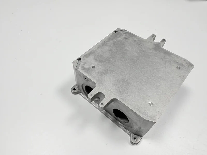
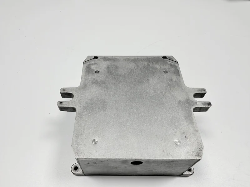
What does an aluminium HPDC enclosure hold?
The box holds a board and a power module, keeps dust and knocks off both, and gives the module a path into the wall for heat. It turns up in control cabinets, drives and power supplies, all indoors. The same casting is a shielding cavity, with conductive inner faces and a lid that closes the opening. HPDC fills a steel die under high pressure; gravity casting lets metal fill a mould under its own weight.
The frame is the band around the opening, and the opening face is the milled land the lid presses on. The sealing face is the step inside the flange, set below the opening face so a gasket would stand proud of it. Four walls close the box, ribs cross the floor and walls, M3 bosses stand inside the cavity, mounting ears sit outside, and two round windows open in a side wall.
A drawing that names these features lets a foundry price them, while an outline alone leaves the mill, the tap, the mask and the gauges to guesswork.
| Part | Feature it sets | Criterion (mm) | If it is wrong |
|---|---|---|---|
| Frame | The band the mill clamps and the lid lands on | 0.10 | A frame that moves takes the face with it |
| Opening face | The milled land under the lid | 0.10 | A rocking face puts the lid out of square |
| Sealing face | The step inside the flange, below the opening face | No flatness call; step depth by drawing | A burr or a dip leaves the step uneven |
| Window edge | The band between a cutout and the flange | 2.5 mm band, same as the wall | The band thins and the wall bows |
| Wall | The skin between the ribs | 2.5 | A thin patch fills short or dents |
| Rib | The last-freezing zone at the root | 2.0 | A rib that never fills leaves the wall to flex |
| Boss | The thread and the board's fixing points | Ø0.2 | A short or off-position boss fails the thread check |
| Mounting ear | The bolt that ties the box to a panel | ±0.3 | A slot off position pulls the frame out of square |
Why is the wall 2.5 mm and the rib 2.0 mm?
The wall runs 2.5±0.2 mm, a drawing target, and the figure is the compromise between fill, weight and sink. A heavier wall fills more easily, adds mass and sinks more, while a thinner one saves weight and risks a short fill. Ribs at 2.0 mm stiffen the wall without adding a second heavy section.
Typical process values for this section pair: the melt runs 650–680 °C into a die held at 200–230 °C, at 70–90 MPa, on a 55–75 s cycle, all typical values.
Shot weight follows the wall, so it is quoted twice, once in the die and once in the metal. The wall thickness starting point works the same trade-off from the other side.
Which three features set the enclosure accuracy?
Three features carry the tolerances: the opening face at 0.10 mm, the M3 boss positions within Ø0.2 mm, and the wall at 2.5±0.2 mm. The outline is 120×90±0.3 mm.
Two of the three come off the die. The wall and the boss positions are cut in the steel, while the opening face cannot be: it depends on the mill and on being the datum.
Each of the two round windows takes a disc out of a side wall, and the band left around it carries the same 2.5 mm section. That band is what holds the wall between the window edge and the flange.
Draft is a design rule on every wall so the part leaves the die, and the angle is pending foundry sign-off.
Why is the opening face machined after casting?
The die leaves its own variation in the face, and ejection moves the frame, so milling comes after casting. The opening face then becomes the datum, and the top face follows it.
The route is casting, trimming, vibratory finishing, milling of the opening face and the top face, tapping, cleaning, coating and final inspection.
Why are the M3 bosses cast and then tapped?
A boss is cast because the die raises it in the same shot; a standoff added later is another part and another fastener. The thread cut comes after milling, so the hole follows the opening-face datum instead of the as-cast skin.
Position holds to Ø0.2 mm, checked on a CMM, and the thread passes a go/no-go gauge plus a 2.5 N·m torque check.
Tapping after milling adds a handling step, and a cast thread would save that step while removing the second chance to correct a hole.
Why does the cavity get conductive oxidation?
The cavity is the shield, so its inner faces take conductive oxidation at 0.3–1.0 µm to MIL-DTL-5541 Type II, with contact resistance at 2.5 mΩ or less.
The outside takes powder at 60–80 µm for appearance and corrosion, with adhesion to ISO 2409 grade 1 or better. The two finishes meet at the flange, and masking covers the mating faces before either finish goes on.
An even film on the seat would lift the lid by the film thickness and break the conductive lap at the flange, so the mating faces stay uncoated. Two finishes mean two mask drawings and two inspection lines, both labour rather than metal.
Which gauges prove an enclosure?
Seven gauges cover the five failure points. A surface plate and a feeler gauge settle the opening face, and a CMM reads boss position. Threads take an M3 go/no-go gauge and a torque wrench, while the coating takes a film thickness gauge, a cross-hatch cutter and a D65 lamp.
A number means little unless the report names the instrument and whether the part sat clamped; a feature with no gauge stays unproven.
When does an enclosure fail in service?
Five points fail: the opening face, the rib root, the M3 thread, an M3 hole plugged by coating and boss position. The rib root is the last-freezing zone where the 2.0 mm rib meets the 2.5 mm wall.
Each point reaches the user as a different symptom, from a lid that will not seat to a board that will not drop onto its bosses.
Service bounds the design. The box runs indoors, in a cabinet or on an industrial site, with oil and vibration, and no outdoor or salt-spray exposure is claimed.
When does the die stop paying for itself?
A single-cavity die rated at 150,000 shots is a design target pending foundry sign-off. The die is paid once and every later shot spreads that cost, so a short batch carries the largest share per part.
A folded sheet box needs no die and wins on a short run, but a seam runs along every corner and the shielding path is harder to close. An extruded profile with end caps keeps tooling low and limits the shape to one section.
In a folded box the ribs are bends, the ears are tabs and the windows are punched openings in the same sheet. An extruded profile carries its ribs in the section and needs end caps; only the bosses and the fasteners are added on either route.
The drawing names the opening face as the datum, plus the wall, the rib, the M3 positions and the finish split with its mask list. It also gives the batch size and the service condition.
The route holds while the batch can carry that 150,000-shot die, and the wall thickness is a drawing target. The melt and die window is a separate check. Past those, a folded or extruded box is the better buy, and an aluminium shell cover case shows the same release checks on a cast part.
What should a design review settle on this box?
A design review fixes five items before the die is cut. They are the opening face as datum, the wall and the rib, the M3 positions, the finish split and its mask list, and the batch and service condition.
FAQ