How Can Drawings Be Prepared for Custom Zinc Die Cast Parts?
How Can Drawings Be Prepared for Custom Zinc Die Cast Parts?
Drawings for custom zinc die cast parts should define critical dimensions, cosmetic surfaces, material requirements, machining areas, surface finish, tolerances, assembly interfaces, annual volume and inspection points. Clear drawings help suppliers evaluate tooling, casting, machining and quality control accurately.
1. Why 3D Models and 2D Drawings Serve Different Purposes
A 3D model helps the supplier review part geometry, wall thickness, parting direction, draft angles and tooling feasibility. A 2D drawing defines dimensions, tolerances, datum surfaces, inspection requirements, cosmetic areas and surface finish notes. Both are important for a reliable zinc die casting quotation and tooling review.
If buyers only provide a 3D model, the supplier may not know which dimensions are critical. If buyers only provide a rough 2D drawing without a model, it may be difficult to evaluate mold structure and manufacturability.
Drawing Detail | Why It Matters |
|---|---|
Critical dimensions | Define CNC machining, tolerance control and inspection priorities. |
Cosmetic surfaces | Guide parting line, gate, ejector mark and finishing decisions. |
Machined areas | Determine machining allowance, fixture planning and cost. |
Surface finish | Defines post-processing, coating, appearance and protection needs. |
Assembly interfaces | Determine fit, function, datum planning and testing requirements. |
Annual quantity | Influences tooling strategy and mass production planning. |
2. What Critical Information Should Be Marked on the Drawing?
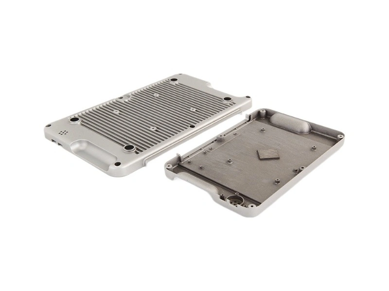
Buyers should mark functional holes, threaded areas, locating surfaces, sealing faces, hinge areas, snap-fit features, visible faces and any surfaces that need machining. Machined surfaces should be separated from as-cast surfaces so the supplier can plan tooling allowance and post-machining correctly.
Cosmetic surfaces should also be marked early. If they are not defined before tooling, parting lines, gate marks or ejector marks may appear on visible areas. Neway can support drawing preparation for zinc die casting and zinc die casting design review before tooling begins.
3. How Drawings Affect Tooling and Post-Machining
Good drawings help the supplier plan tooling for zinc die cast parts, parting line, gate location, ejector position, machining allowance and inspection points. If post-machining areas are not marked, the casting may not leave enough stock for accurate machining.
When drawings clearly separate as-cast surfaces and machined surfaces, Neway can better evaluate post-machining requirements and avoid unnecessary cost on non-functional areas.
Drawing Risk | Possible Result | Recommended Action |
|---|---|---|
Only 3D model is provided | Critical tolerances and inspection points are unclear. | Add a 2D drawing with functional dimensions. |
Cosmetic faces are not marked | Tooling marks may appear on visible surfaces. | Mark visible surfaces before mold design. |
Machined areas are not defined | Machining allowance may be missing or cost may be inaccurate. | Separate machined and as-cast surfaces. |
Surface finish is unclear | Quotation may miss post-processing or coating requirements. | Specify finish type, coating thickness and appearance standard. |
Assembly information is missing | Supplier cannot identify functional features. | Provide mating part details or assembly requirements. |
4. How Neway Supports Manufacturable Zinc Die Cast Part Design
If buyers are unsure whether drawings are suitable for custom zinc die cast parts, Neway can review the design before tooling. Through manufacturable zinc die cast part design, buyers can reduce mold modification, machining conflicts, finishing issues and assembly failure.
Summary
Buyer Question | Recommended Drawing Preparation |
|---|---|
Is a 3D model enough? | No. A 2D drawing should define tolerances, critical dimensions and inspection points. |
Should cosmetic surfaces be marked? | Yes. They affect tooling layout, finishing quality and packaging protection. |
How should machining areas be shown? | Separate machined surfaces from as-cast surfaces and reserve machining allowance. |
When should Neway review the drawing? | Before tooling, especially when the part has appearance, assembly or post-machining requirements. |