What wall thickness is recommended for zinc die casting parts?
What wall thickness is recommended for zinc die casting parts?
The recommended wall thickness for most zinc die casting parts is typically about 1.0 mm to 3.0 mm for standard production designs, with many parts performing best in the 1.2 mm to 2.5 mm range. Zinc alloys have excellent fluidity, so they can support thinner walls than many other casting materials, but the ideal thickness still depends on part size, flow length, structural load, flatness requirements, cosmetic expectations, and whether the design includes ribs, bosses, threads, or post-machined features.
1. Recommended Wall Thickness Ranges for Zinc Die Casting
Feature Type | Recommended Thickness | Design Guidance | Typical Use |
|---|---|---|---|
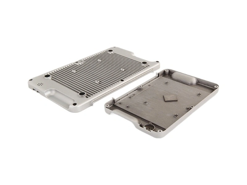
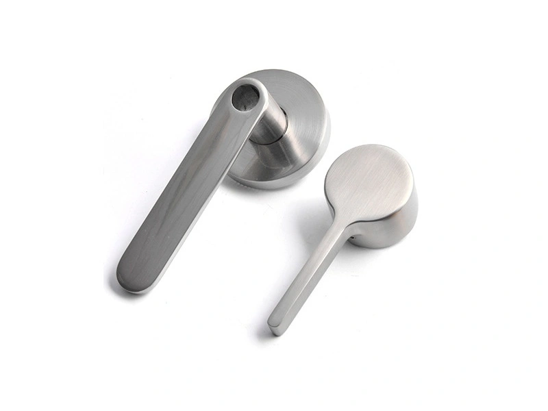
Main walls | 1.2–2.5 mm | Best range for balanced fill, dimensional control, and surface finish | General housings, brackets, handles, covers |
Thin-wall sections | 0.8–1.2 mm | Possible with zinc due to strong fluidity, but requires careful gating and process control | Electronics shells, decorative parts, small precision components |
Heavier structural walls | 2.5–4.0 mm | Useful where added stiffness is needed, but should be designed to avoid sink and shrinkage issues | Loaded hardware, support bodies, reinforced housings |
Ribs | 50–70% of main wall | Helps improve stiffness without adding excessive mass or causing local defects | Flat panels, covers, structural shells |
Bosses and local features | Similar to or slightly below main wall | Avoid sudden thick zones that increase porosity and shrink risk | Screw seats, locating features, inserts |
2. How Wall Thickness Affects Part Quality
Wall Thickness Condition | Main Effect | Typical Risk |
|---|---|---|
Too thin | Harder filling and greater sensitivity to flow interruption | Misruns, short shots, weak edges, inconsistent fill |
Well balanced | Stable fill, good finish, strong dimensional consistency | Lowest overall risk in production |
Too thick | More difficult solidification control and larger thermal mass | Shrinkage, porosity, sink marks, warpage, longer cycle time |
Uneven transitions | Non-uniform cooling and internal stress concentration | Distortion, cosmetic defects, tolerance variation |
3. Why Uniform Wall Thickness Is More Important Than Maximum Thickness
In zinc die casting, wall thickness should not be judged only by how thin the alloy can flow. The more important rule is to keep wall sections as uniform as possible. A consistent wall helps the part fill evenly, cool evenly, and eject with lower distortion risk. Even when zinc alloys can cast thin sections successfully, large thickness jumps between one area and another often create more problems than an overall thin design.
That is why many successful parts are designed with moderate, uniform walls and then strengthened with ribs instead of relying on thick solid sections. For OEM parts that must also hold tight tolerances, this approach usually improves both dimensional stability and cosmetic consistency. It is especially useful when the part later requires post machining or assembly-critical fit.
4. Practical Guidelines by Part Type
For general-purpose housings and covers, a wall thickness around 1.2 mm to 2.0 mm is often the most efficient choice. This range usually supports good fill, attractive surface finish, and stable production economics.
For small cosmetic parts and detailed hardware, thinner walls around 0.8 mm to 1.2 mm may be possible because zinc has strong casting fluidity. These designs are common in visible consumer parts, especially where sharp detail and fine features matter.
For functional hardware and stronger load-bearing parts, wall thicknesses around 2.0 mm to 3.0 mm are often more practical. Instead of increasing all sections, designers should thicken only where necessary and support the rest of the structure with ribs or gussets.
For larger parts, the wall may need to increase beyond the standard range, but the design should still avoid heavy isolated masses. In these cases, the geometry should be reviewed together with design and engineering input to keep filling and cooling balanced.
5. Design Mistakes to Avoid
Common Mistake | Why It Is a Problem | Better Approach |
|---|---|---|
Using overly thick walls for strength | Can increase porosity, sink, and cycle time | Use ribs and better geometry instead of mass alone |
Designing abrupt wall transitions | Creates uneven cooling and distortion | Use gradual transitions and blended geometry |
Pushing walls too thin without process review | Raises risk of incomplete fill and weak features | Confirm with alloy, gate, and part-size evaluation |
Making bosses much thicker than adjacent walls | Encourages shrinkage and local defects | Core out thick zones and keep feature walls balanced |
6. Summary
If you need... | Recommended wall thickness |
|---|---|
Standard zinc die cast parts | 1.2–2.5 mm |
Very thin detailed sections | 0.8–1.2 mm |
Heavier functional parts | 2.5–4.0 mm where necessary |
Ribs | 50–70% of main wall |
Best overall design rule | Keep walls as uniform as possible |
In summary, the recommended wall thickness for zinc die casting parts is usually 1.0 mm to 3.0 mm, with 1.2 mm to 2.5 mm being the most practical range for many OEM designs. The best result comes not from making the wall as thin or thick as possible, but from keeping the section uniform, using ribs for stiffness, and matching the thickness to the part’s size, function, and finish requirements. For related information, see the minimum wall thickness achievable for zinc alloy die castings, how dimensional tolerance and flatness are ensured in large cast parts, and how Zamak alloy properties affect dimensional stability and surface finish.