How Tooling Affects Die Casting Cost, Quality and Production Stability
How Tooling Affects Die Casting Cost, Quality and Production Stability
Tooling is one of the most important decisions in a die casting project. For buyers, engineers, project managers, and product developers, tooling is not only a mold price. It affects part quality, dimensional stability, surface appearance, production efficiency, CNC machining allowance, trial sample results, mold life, scrap rate, and long-term unit cost.
Many buyers compare die casting suppliers by tooling price only. This can be risky. A low-cost mold may look attractive at the quotation stage, but poor mold design can lead to porosity, shrinkage, cold shuts, flash, burrs, deformation, unstable dimensions, high rework cost, slow cycle time, and frequent tooling modification.
A good die casting tooling plan should connect part design, material selection, annual demand, production volume, surface treatment, cosmetic surfaces, functional surfaces, CNC machining areas, inspection requirements, and mass production goals. When tooling is planned correctly before production, buyers can reduce trial mold corrections, improve batch stability, and control total manufacturing cost more effectively.
What Is Tooling in Die Casting?
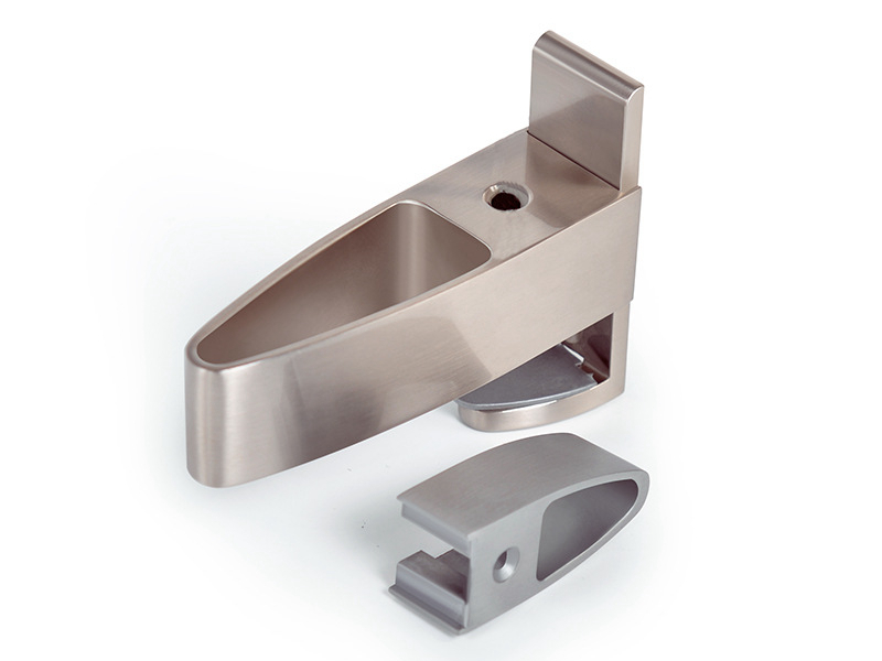
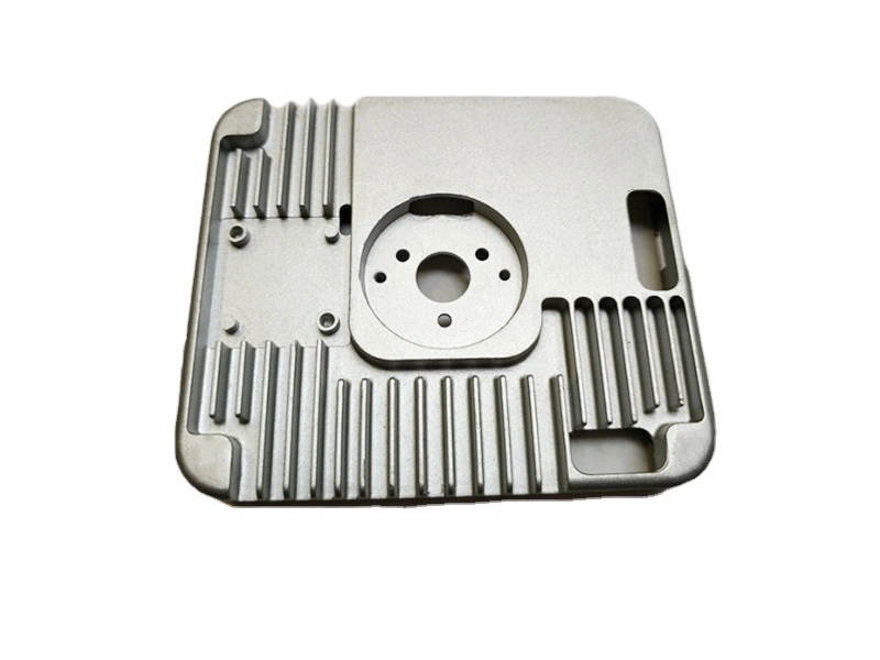
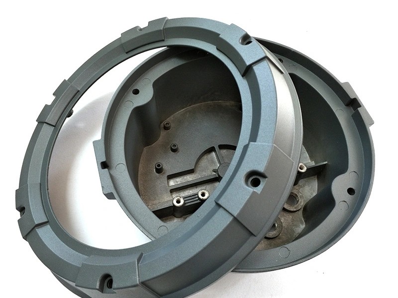
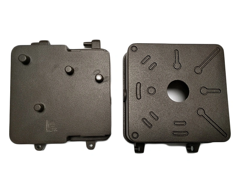
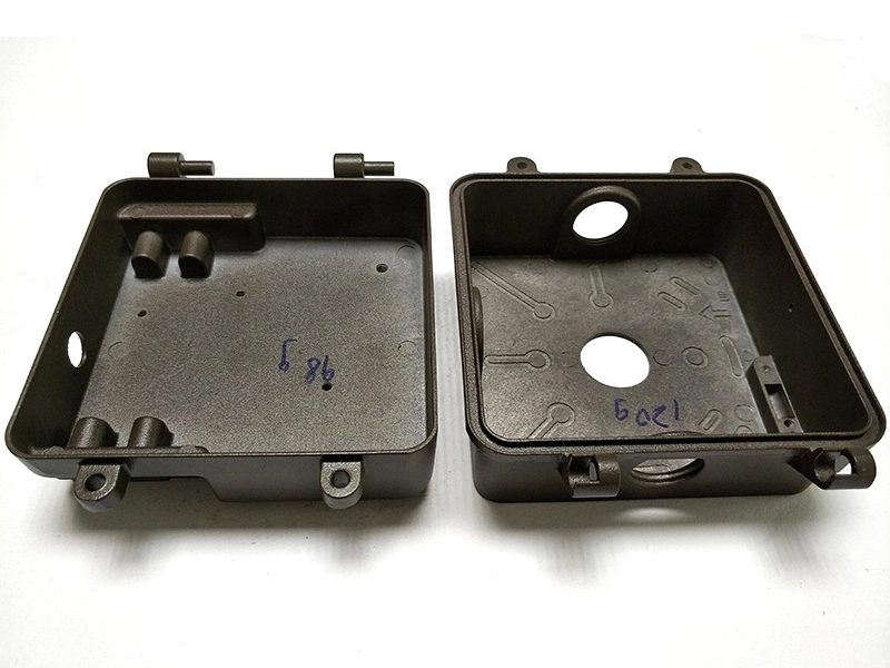
Tooling in die casting refers to the mold and related forming structures used to produce die cast metal parts. It usually includes mold cavities, cores, gates, runners, vents, ejector systems, cooling systems, inserts, sliders, and parting line structures.
Tooling determines whether molten metal can fill the cavity properly, whether trapped air can escape, whether the part can cool evenly, whether the part can be ejected safely, and whether the same part can be repeated consistently during production.
For medium and high-volume projects, die casting tooling is the foundation of production stability. It affects part dimensions, appearance, burrs, porosity, machining allowance, cycle time, and long-term manufacturing cost.
Tooling Element | Main Function | Buyer Impact |
|---|---|---|
Mold cavity | Forms the final part shape | Affects geometry, surface quality, and repeatability |
Core | Forms internal features, holes, pockets, or complex structures | Affects part function and mold complexity |
Gate and runner | Controls molten metal flow into the mold | Affects filling quality, flow marks, and porosity risk |
Venting system | Allows trapped air and gas to escape | Reduces internal defects and gas porosity |
Cooling system | Controls solidification and mold temperature | Affects dimensional stability and cycle time |
Ejector system | Pushes the part out of the mold | Affects surface marks, deformation, and production reliability |
Why Tooling Is Critical Before Die Casting Production
Tooling is critical because the mold design controls how the part is formed before any mass production begins. If the tooling design is not suitable for the part structure, material, tolerance, and production quantity, problems may appear during trial samples or batch production.
Gate position affects metal flow, flow marks, filling balance, and porosity risk. Venting design affects internal gas defects. Cooling design affects shrinkage, deformation, dimensional stability, and cycle time. Parting line position affects appearance, flash, and post-processing workload. Ejector pin position affects visible surfaces, assembly faces, and deformation risk.
Good tool and die making helps buyers reduce production risk before the first batch begins. Poor tooling may increase mold repair, trial corrections, surface defects, CNC machining problems, and final inspection failure.
Tooling Design Area | What It Affects | Possible Problem if Poorly Planned |
|---|---|---|
Gate position | Metal flow, filling balance, surface marks | Flow marks, cold shuts, porosity, uneven filling |
Venting design | Air release during filling | Gas porosity and internal defects |
Cooling system | Solidification, shrinkage, cycle time | Warpage, shrinkage, unstable dimensions |
Parting line | Flash position and cosmetic appearance | Visible parting marks and extra finishing cost |
Ejector layout | Part release and surface marks | Ejector pin marks, deformation, sticking |
Mold structure | Maintenance, mold life, production repeatability | Frequent repair and unstable mass production |
What Affects Tooling Cost?
Tooling cost is affected by more than the mold size. Buyers should evaluate tooling cost together with part complexity, material choice, tolerance requirements, cosmetic requirements, cavity number, production volume, tool life, cycle time, and maintenance risk.
A simple single-cavity mold for a small part will not cost the same as a large multi-cavity mold for a complex structural component. Cosmetic parts may also need better gate planning, parting line control, ejector layout, and surface finish control than hidden functional parts.
Cost Factor | How It Affects Tooling | Buyer Concern |
|---|---|---|
Part size | Larger parts need larger molds | Higher tooling cost |
Part complexity | More ribs, bosses, and undercuts increase mold complexity | More design review needed |
Cavity number | Multi-cavity molds improve output but increase mold cost | Balance tooling cost and unit cost |
Material choice | Aluminum, zinc, and copper alloys affect mold design differently | Process stability |
Tolerance requirement | Tight dimensions may require better mold precision | Higher tooling and inspection cost |
Surface requirement | Cosmetic parts need better gate, parting line, and ejector planning | Appearance control |
Production volume | High-volume projects may need stronger production tooling | Long-term cost control |
How Tooling Affects Part Quality
Tooling quality directly affects die cast part quality. A well-designed mold can improve dimensional consistency, reduce internal defects, control flash and burrs, improve surface appearance, and support stable production across repeated batches.
Reasonable gate and venting design can reduce porosity, cold shuts, and trapped gas. Stable cooling can reduce shrinkage, warpage, and dimensional variation. Proper parting line planning can reduce visible defects and post-processing workload. Good ejector layout can reduce deformation and ejector pin marks.
Tooling also affects later CNC machining after die casting. If the casting has unstable dimensions or insufficient machining allowance, holes, threads, sealing faces, and datum surfaces may become difficult to machine consistently.
Quality Area | How Tooling Affects It | Risk from Poor Tooling |
|---|---|---|
Dimensional consistency | Mold precision and cooling stability help repeat the same dimensions | Unstable assembly fit and inspection failure |
Porosity and cold shuts | Gate and venting design affect filling and gas release | Internal defects and weak part performance |
Shrinkage and deformation | Cooling and wall thickness control affect solidification | Warpage, sink marks, and dimensional drift |
Surface appearance | Parting line, ejector position, and gate location affect visible faces | Cosmetic defects and finishing rework |
Burrs and flash | Mold fit and parting line quality affect flash control | Extra deburring, polishing, and rework cost |
CNC machining allowance | Tooling must leave enough material for critical machined areas | Scrap, poor final dimensions, and machining problems |
How Tooling Affects Unit Cost
Tooling cost is the upfront investment, while unit cost is the long-term production cost. Buyers should not evaluate a die casting project only by mold price. The better decision is to compare tooling cost, unit cost, tool life, scrap rate, cycle time, maintenance cost, and production stability together.
When annual demand is high, tooling cost can be spread across more parts. A multi-cavity mold may increase upfront tooling cost, but it can improve production output and reduce unit cost if the volume is high enough. Stronger production tooling may also reduce downtime, rework, and scrap during long-term production.
Poor tooling may appear cheaper at the beginning, but it can increase mass production cost through slow cycle time, frequent repairs, flash removal, dimensional instability, scrap, and higher inspection pressure. For buyers sourcing die cast metal parts, total manufacturing cost is more important than tooling price alone.
Cost Area | Good Tooling Impact | Poor Tooling Risk |
|---|---|---|
Cycle time | Stable cooling and ejection improve production efficiency | Longer cycle time and lower output |
Scrap rate | Better filling and defect control reduce rejected parts | Higher scrap and material waste |
Rework cost | Good mold fit reduces flash, burrs, and surface defects | More deburring, polishing, and correction work |
CNC machining time | Stable cast blanks reduce machining variation | More fixture adjustment and inspection work |
Maintenance cost | Proper mold structure improves tool life | Frequent repairs and production interruption |
Unit cost | Higher production stability lowers long-term cost | Cheap tooling may create expensive mass production problems |
When Should Buyers Start Tooling?
Buyers should start tooling when the project is technically and commercially ready. Tooling should usually begin after the design is mostly frozen, material is confirmed, annual demand is reasonably stable, assembly relationship is verified, surface treatment requirements are clear, and critical CNC machining areas are defined.
If the project has completed prototype validation and the buyer is preparing to move into small batch production or mass production, tooling becomes the next logical step. At this stage, the supplier can design the mold based on confirmed geometry, material, tolerance, cosmetic surface, functional surface, and production volume.
Buyers should avoid starting tooling too early if the design is still changing, material is not confirmed, product function has not been tested, appearance requirements are unclear, annual demand is unstable, or target cost has not been reviewed. Starting too early may lead to expensive tooling modification later.
Ready for Tooling | Not Ready for Tooling |
|---|---|
Design is mostly frozen | Design is still changing frequently |
Material is confirmed | Material has not been selected |
Annual demand is stable | Market demand is unclear |
Prototype validation is completed | Product function has not been tested |
Assembly relationship is verified | Fit and interference risk are still unknown |
Surface treatment requirements are clear | Appearance and coating requirements are not defined |
CNC machining areas are confirmed | Critical machined areas are still uncertain |
What Buyers Should Confirm Before Tooling
Before starting tooling, buyers should confirm all major technical and commercial requirements. A 3D model alone is not enough for accurate tooling planning because tooling depends on material, tolerance, surface requirement, machining areas, production volume, and inspection needs.
Important information includes 2D drawing, 3D model, material requirement, annual demand, single order quantity, tolerance requirement, assembly requirement, surface treatment requirement, cosmetic surface marking, critical dimensions, CNC machining areas, use environment, sample validation needs, target cost, and mass production plan.
Information to Confirm | Why It Matters for Tooling | Risk if Missing |
|---|---|---|
2D drawing | Shows tolerances, notes, critical dimensions, and inspection requirements | Wrong tooling assumptions |
3D model | Shows geometry, wall thickness, ribs, bosses, and complex features | Incomplete mold design review |
Material requirement | Different alloys affect filling, cooling, and mold design | Process instability |
Annual demand | Affects cavity number, tooling strength, and production strategy | Wrong tooling investment level |
Tolerance requirement | Defines which areas need tighter control | Unstable dimensions or unnecessary cost |
Assembly requirement | Shows how the part fits with other components | Fit problems after sampling |
Surface treatment requirement | Affects parting line, ejector position, and cosmetic surface planning | Visible defects and finishing rework |
Cosmetic surface marking | Identifies faces that must avoid gate marks, ejector marks, or parting lines | Appearance disputes |
CNC machining areas | Defines where machining allowance is needed | Insufficient stock for post machining |
Mass production plan | Helps define mold life, cavity number, and maintenance strategy | Tooling may not match production needs |
Can Tooling Be Modified After Trial Samples?
Die casting tooling can often be modified after trial samples, but modification usually affects cost and lead time. Tooling modification may require mold welding, insert adjustment, gate changes, ejector changes, machining correction, cavity polishing, or local design changes.
Common reasons for tooling modification include hole position deviation, assembly interference, unreasonable wall thickness, local shrinkage, porosity problems, cosmetic surface defects, unsuitable parting line or ejector position, insufficient CNC machining allowance, and customer design changes.
Tooling modification is sometimes necessary, but buyers should try to reduce modification risk before mold production. The more complete the DFM review before tooling, the lower the risk of expensive changes after trial samples.
Tooling Modification Reason | What It May Require | Buyer Impact |
|---|---|---|
Hole position deviation | Local mold correction or machining process adjustment | Sampling delay and inspection review |
Assembly interference | Design change or cavity modification | Additional engineering review |
Wall thickness issue | Part design or mold adjustment | Higher risk of shrinkage or deformation |
Porosity problem | Gate, venting, or process adjustment | More trial runs and quality testing |
Cosmetic surface defect | Polishing, gate change, ejector adjustment, or surface repair | Appearance approval delay |
Insufficient machining allowance | Tooling correction or machining process change | Risk of scrap or poor final dimensions |
Customer design change | Mold modification or new insert | Extra cost and longer lead time |
How to Reduce Tooling Risk in Die Casting Projects
Buyers can reduce tooling risk by working with a supplier that performs DFM review before mold production. The review should check wall thickness, ribs, bosses, corner radii, draft angles, parting lines, gate locations, venting, cooling, ejector positions, cosmetic surfaces, functional surfaces, and CNC machining areas.
For tooling for aluminum die cast parts, buyers should pay attention to thermal behavior, porosity control, cooling, and machining allowance. For tooling for zinc die cast parts, buyers should pay attention to fine details, cosmetic surfaces, small features, and dimensional repeatability.
After trial samples, buyers should review dimensional reports, surface appearance, assembly fit, machining results, and inspection standards before approving mass production. This helps prevent small trial problems from becoming large batch production problems.
Risk Reduction Step | What to Check | Buyer Benefit |
|---|---|---|
DFM review before tooling | Wall thickness, ribs, corners, draft, and manufacturability | Reduces mold modification risk |
Gate, venting, cooling, and ejector planning | Metal flow, gas release, thermal control, and part release | Improves casting stability |
Cosmetic and functional surface definition | Visible surfaces, assembly areas, sealing faces, and contact surfaces | Reduces appearance and functional disputes |
CNC machining area confirmation | Holes, threads, datum faces, sealing surfaces, and flatness areas | Improves post-machining planning |
Prototype or sample validation | Fit, function, surface, dimensions, and material behavior | Reduces mass production risk |
Trial sample report review | Dimensional report, surface standard, casting defects, and machining results | Confirms problems before batch production |
Inspection plan before mass production | Critical dimensions, cosmetic inspection, and functional testing | Improves batch consistency and delivery confidence |
Neway supports die casting tooling projects that require design review, tool and die making, aluminum die casting, zinc die casting, CNC machining after die casting, custom metal casting, sample validation, and production support. For buyers preparing to move from prototype to mass production, early tooling planning can reduce trial mold risk, improve part quality, and support stable production.
FAQ