
What Is a Split Bearing Housing? A356 Casting and Bore Fit
A split bearing housing carries a shaft or a bearing in a two-piece body: a base half, and a cap bolted over it. Gravity casting forms both halves and their four mounting ears in a steel mold; the bore is cut later, once the halves are bolted.
This housing is an A356-T6 casting of 120×95×70 mm and 420±30 g, with a 5–8 mm wall and a Ø60 H8 bore. Every figure is a drawing target, not a sample reading.
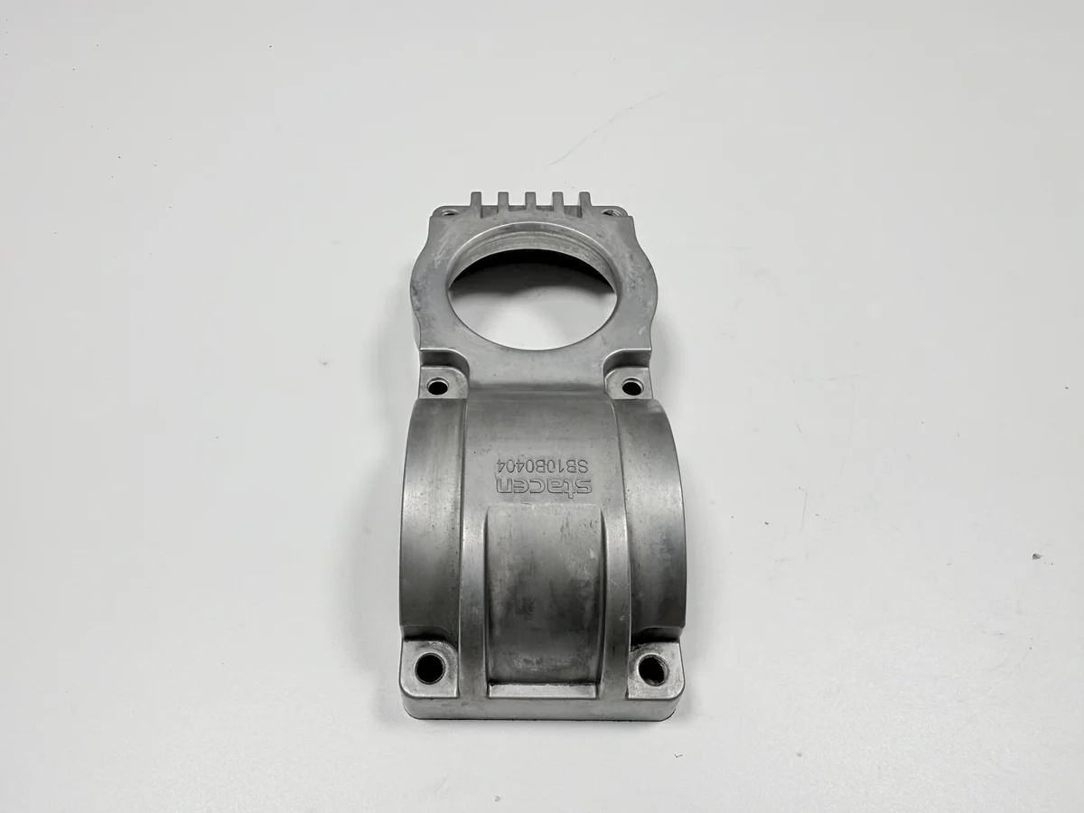
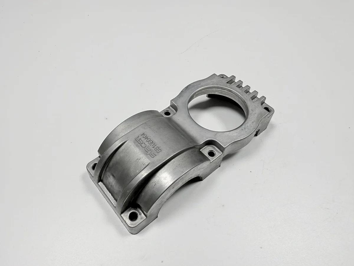
What does a split bearing housing hold?
The housing holds one of two things: a bearing outer ring pressed into the bore, or a shaft journal resting on the half-round seat. The seat is the half-round face that the split line cuts in two, so the cap closes over the journal from above. Four mounting ears bolt the body to a frame. The bearing position follows the bore axis and the mounting face, so both are datums, the reference surfaces every reading starts from.
Why is the housing split into two halves?
The split lets a shaft go in from above rather than through a closed ring, which suits a housing at the end of a gearbox or conveyor pulley. The halves are bolted and bored as one body afterwards, so the joint belongs to the accuracy chain rather than to the lid.
Split faces are held flat to 0.05 mm for that reason. A face that rocks closes at the bolts and opens at the bore, and the clamp load pulls the bore out of round. The pair is machined together, so the halves stay a matched set and a cap from another set is not a spare.
Which three surfaces set the housing accuracy?
Three surfaces carry the tolerances: the Ø60 H8 bore, the two split faces, and the mounting face. H8 is the hole tolerance band on the drawing.
The datums are the mounting face and the bore axis, so squareness of 0.05 mm is read between them, and the half-round seat is held coaxial to the bore within 0.05 mm. The flange holes at 4×Ø9 sit within a Ø0.3 mm position tolerance, a fourth check rather than a fourth datum.
Why is the bore bored after bolting?
Bolting comes first because each half bored on its own gives the seat and the bore separate axes, and a bearing ring pressed onto two axes wears on one side. The bolts close the joint, the bore moves with that clamp load, and one pass cuts both halves back onto a single axis.
The order is fixed: mill the split faces, bolt the halves, bore, then drill the flange holes. A face milled after the bore would shift the axis the bore was set on. Bolt-up, boring and unbolting are three stations, which is why the step stands as its own line in a quote, not inside plain machining.
Why is A356-T6 used for this housing?
A356 is AlSi7Mg, the same alloy as GB/T 1173 ZL101A, and T6 is the temper: solution treatment, a water quench, then aging. The alloy fills a 5–8 mm wall in a steel mold, machines without tearing, and holds the 420±30 g budget. The pour runs at 700–740 °C in a mold preheated to 250–350 °C, then solution at 535–545 °C and aging at 155–165 °C for 4–6 h, all pending foundry sign-off.
Finish is a shot blast to Sa 2.5 under ISO 8501-1 on the cast faces, with the bore and the split faces left as cut. Anodizing is not confirmed for this part, so a drawing that calls for color or film thickness adds a specification and a cost. Plating or painting follows the same rule and needs masking on the bore and the joint.
Why does a 5–8 mm wall carry a shrink risk?
The wall is 5–8 mm by design, and its thick end sits at the half-round seat. That node freezes last, its feed has already sealed, and the cavity left behind sits below the face the boring tool will cut.
A hole over Ø1 mm scraps the housing; one at Ø1 mm or under passes where the seat is otherwise sound. The call is made by eye on the machined seat, then confirmed with penetrant testing. Because the defect shows only after boring, the cutting time is spent before it appears, and the pour is the one place left to fix it.
Which gauge checks each feature?
Each feature has one gauge: a three-point inside micrometer for the bore and its ovality, a CMM for squareness and coaxiality, and a surface plate with a feeler gauge for the split faces. Flange holes take go/no-go plugs and a trial fit, and the seat takes penetrant testing.
The table sets target, allowed range and gauge side by side, because a reading without the state it was taken in proves little. A bore measured in the fixture and the same bore released give two numbers, and the report has to name which one it holds. That report is what CMM inspection settles.
| Feature | Drawing target | Allowed range | Proved with |
|---|---|---|---|
| Bore | Ø60 H8 | H8 limits, ovality 0.03 mm at most | Inside micrometer, three points |
| Split faces | 0.05 mm flat | 0.05 mm or less | Surface plate and feeler gauge |
| Bore to mounting face | 0.05 mm square | 0.05 mm or less | CMM, face as datum |
| Seat to bore | 0.05 mm coaxial | within 0.05 mm | CMM, bore as datum |
| Flange holes | 4×Ø9 | position Ø0.3 mm | Go/no-go plugs and trial fit |
| Cast surface | Sa 2.5 | ISO 8501-1 grade or better | Comparator |
When does a cast housing fail in service?
The housing fails where the three surfaces reach their limits. A cavity under the seat lets the ring rock, an oval bore pinches the ring and runs hot, and bolt holes off position leave two of the four ears carrying the load. A split face that rocks springs the bore every time the joint is tightened.
Service conditions bound the design. This housing runs indoors, inside equipment, with oil and vibration, and no outdoor or washdown exposure is promised. Past that line the corrosion route and the load path change, and aluminum stops being the right answer.
When should the part be sand cast or cast in iron?
Sand casting takes the large envelope and the one-off, because a pattern costs less than a steel mold and thick sections are normal there; the surface arrives rougher and more faces need cutting. Cast iron takes the case where stiffness outranks weight, at a mass the frame has to carry.
The steel-mold route holds while the wall stays 5–8 mm as drawn, the order can carry the tool, and the service stays indoors. One mold gives one or two parts per shot, pending foundry sign-off, and its cost spreads across the shots that share it, so a short run carries a different tooling share from a long one. Route comparison sits in choosing a casting process and machining against casting; a die-cast and machined hinge shows similar release checks.
Send the drawing with the bore, the split-face flatness and the datum marked, plus the batch size and the service condition. Those five items decide whether the tool is worth cutting and what the first article checks.
FAQ