Metal Casting Applications: Matching Process, Alloy and Production Volume to Part Requirements
The strongest metal casting applications are parts whose geometry, material and repeat demand benefit from forming a near-net shape before selective machining and finishing. Housings with ribs and bosses, thermal bodies with fins, pump bodies with passages, structural supports and compact hardware can all fit this logic, but the part name alone never selects the process.
A poor application decision usually appears later as unnecessary tooling, an inaccessible core, an unstable pressure boundary, excess machining stock, cosmetic rework or a process that does not match annual volume. These problems affect total part cost, validation time and repeat-order consistency more than a simple comparison of casting prices.
A practical selection starts with load, heat, fluid, corrosion, assembly and appearance duties. It then screens alloy families and casting routes, divides as-cast and secondary features, and defines evidence that releases the part. The result is an application-specific route rather than a list of industries that happen to use castings.

What Types of Parts Are Good Applications for Metal Casting?
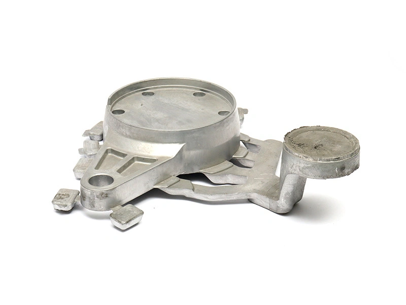
A part is a strong casting candidate when forming the shape removes substantial material waste or repeated setup work while preserving the required feature relationships. Useful signals include three-dimensional walls, ribs and bosses; enclosed or partly enclosed passages; repeated geometry around a housing; a material that is available in an appropriate casting alloy; and demand sufficient to support the selected pattern, die or mold route.
Casting is less attractive when the design changes every few pieces, quantity is extremely low, every surface needs precision machining, or the required material and condition are not compatible with the proposed route. A casting may still be possible, but possibility is not the same as commercial fit. The buyer should compare total finished-part work, not raw casting cost alone.
Part Signal | Why Casting May Help | Boundary to Check | Evidence Before Selection |
|---|---|---|---|
Ribs, bosses and enclosure walls | Forms several structural features in one near-net body | Wall transitions, draft, filling and ejection must be practical | DFM review tied to the actual casting route |
Internal passage or cavity | A core or tool action may avoid machining an inaccessible void | Core support, removal, cleaning and leakage risk | Core concept, passage inspection and functional test plan |
Repeated production geometry | Tooling can stabilize the basic form across later lots | Annual demand must justify tooling and maintenance | Volume forecast, tool ownership and change-control plan |
Localized precision interfaces | Leaves noncritical regions as-cast and machines only CTQs | Datum transfer and machining stock must be controlled | As-cast/machined feature map and inspection method |
Appearance or corrosion requirement | Supports a defined mechanical or coating route after casting | Alloy, porosity, parting line and pretreatment affect finish | Cosmetic-zone map and approved finish sample |
Frequent revision at very low volume | Usually offers little repeat-tooling benefit | Pattern changes and validation may dominate cost | Compare flexible casting, additive pattern and machining routes |
The screening decision should include the delivered condition: raw casting, machined casting, finished component or assembled part. A route that looks economical at the casting gate can lose its advantage if it creates difficult fixturing, repeated sealing repairs or finish rejects. Freeze the functional surface map before selecting the process.
How Housings and Enclosures Use Casting Efficiently
Housings use casting efficiently when the same body must enclose components, carry mounting loads, locate mating parts, manage heat or shielding, and present only a few precision interfaces. The cast shape can integrate ribs, standoffs, cable openings, bosses, gasket lands and external contours. The buyer still needs to decide which features are truly formed and which are drilled, threaded, milled or sealed later.
For an enclosure, build a feature hierarchy. The pressure or environmental boundary comes first, followed by assembly datums, heat paths, fastener loads, connector positions and appearance zones. Thick boss-to-wall junctions, abrupt section changes and long unsupported panels deserve review because they can concentrate shrinkage or distortion. Draft and parting lines must not cross gasket lands or cosmetic zones without an approved disposition.
Housing Feature | Cast-Shape Role | Likely Secondary Control | Release Question |
|---|---|---|---|
Outer shell | Encloses components and establishes overall stiffness | Deburring, texture or protective finish | Are wall transitions and visible zones acceptable? |
Rib network | Transfers mounting or handling load without a solid wall | Usually retained as-cast | Does the rib path support the actual load case? |
Bosses and standoffs | Creates local fastening and component support | Drilling, tapping or insert installation where required | Are pull-out load, stock and position defined? |
Gasket land | Provides stock around the enclosure boundary | Machining and surface inspection | Are flatness, roughness and coating exclusion controlled? |
Connector opening | Forms a near-net port and surrounding reinforcement | Machining or gauging according to fit | Is its position tied to a stable assembly datum? |
Medium- or high-volume enclosures with complex walls may be candidates for aluminum die casting, while larger or lower-volume housings may point toward another route. The correct choice depends on dimensions, wall flow, internal geometry, appearance, quantity and validation burden. Do not label an enclosure as pressure-tight or ingress-rated from process name alone.
How Heat Sinks and Thermal Components Change Alloy Choice
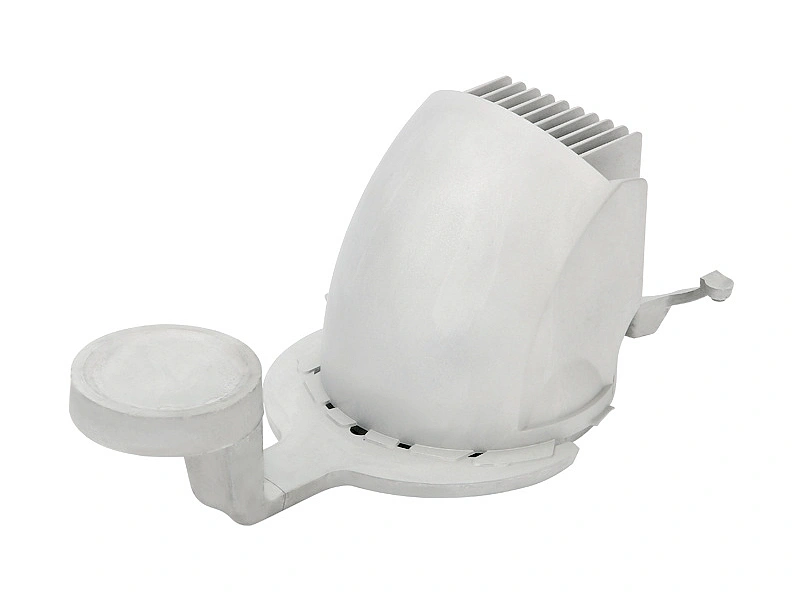
Thermal components change the application decision because alloy conductivity is only one part of the heat path. The casting route must also fill the fin field, preserve fin roots, maintain the base section and support any machined interface. Published material data should be compared under compatible alloy condition, test method and temperature; pure-aluminum data cannot be assigned to a production casting.
Fin height, spacing, draft, orientation and distance from the gate affect fill risk. A narrow fin that exists in CAD but is incomplete, distorted or damaged after ejection provides no thermal advantage. The base must provide enough stock for the contact surface without opening unacceptable discontinuities, and the datum scheme must define how flatness is measured after unclamping.
Surface treatment may improve environmental durability or appearance but can change contact resistance, dimensions and emissivity. Masking around the thermal interface, fastener seats and grounding zones must be explicit. A useful approval compares finished parts under controlled heat input, ambient, airflow, interface material, mounting torque and sensor position. This keeps the material decision connected to the complete component rather than a single table value.
For heat-sink material screening, published cast aluminum heat-sink alloy guidance can provide a starting point. The project still needs cavity-specific fill evidence, a traceable material lot, base inspection and a test that represents the intended assembly.
What Pump and Valve Bodies Require From Casting
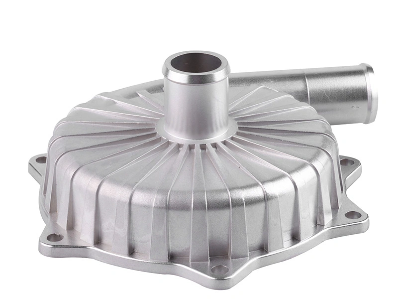
Pump and valve bodies require the casting route to create a stable fluid boundary before machining exposes ports, bores, seats and seal faces. Internal passages may be formed by sand cores, soluble or mechanical core concepts, tool actions or another process-specific method. The passage geometry, wall around the passage, core location and removal route must be assessed together.
A fluid housing drawing should separate nominal pressure duty, proof condition, leak criterion, fluid, temperature, corrosion exposure and cleanliness. These are different requirements. A proof-pressure test checks behavior under a defined pressure and duration; a leakage test measures or detects escape under a stated medium, pressure and method. Neither result can be interpreted correctly without the tested revision, part state, fixture and acceptance limit.
Fluid-Body Control | Design or Process Concern | Evidence | Do Not Assume |
|---|---|---|---|
Cored passage | Core support, shift, erosion, removal and residual media | Section, dimensional method, borescope or functional flow check as applicable | Visible outer quality proves internal geometry |
Pressure boundary | Local wall, junctions, porosity sensitivity and process stability | Defined leak or pressure test on the correct part state | Every casting from the same process has the same pressure rating |
Seal face | Stock cleanup, flatness, roughness and opened discontinuities | Machining and surface record under a defined datum setup | Coating or sealant corrects an unsuitable machined face |
Port and thread | Position to passage, thread form, depth and cleanliness | Gauge, position and cleaning evidence | A cast pilot guarantees final thread alignment |
Wetted material | Compatibility with fluid, temperature and galvanic contacts | Controlled alloy requirement and application-specific review | Aluminum or copper alloy names alone prove compatibility |
A published A413 pump and valve body application page can illustrate one alloy-and-part context, but it does not approve A413 for every fluid, pressure or geometry. The buyer must retain ownership of the actual duty, standard, test criterion and substitution rule.
How Brackets and Structural Supports Balance Weight and Strength
Brackets and supports benefit from casting when load paths can be formed with ribs, flanges, bosses and locally thick sections rather than machining a solid billet. The design goal is not simply minimum weight. It is sufficient stiffness and strength at mounts, joints and fasteners while keeping section transitions castable and distortion manageable.
Map each external load to its reaction point. Ribs should carry that path into the body rather than terminate in a lightly supported wall. Bosses need appropriate junctions and local material, but oversize mass can create hot spots. Bolt preload, insert pull-out, impact, vibration, fatigue and static overload are separate cases; only those relevant to the product should enter the validation plan.
Alloy selection follows the load and environment as well as process availability. Aluminum can reduce mass and provide useful thermal behavior. Zinc can support compact detail and finish but adds density. Copper alloys may serve conductivity, wear or specific environmental goals but introduce different casting and cost constraints. Ferrous alloys may suit larger sand-cast supports where section size, stiffness and wear outweigh mass. These are screening directions, not universal rankings.
Before approving a support, correlate the material specification, drawing revision, casting condition, machined holes and test fixture. If heat treatment is proposed, define the alloy, condition, distortion risk and evidence rather than adding a generic temper note. A structural label or end-use image cannot replace an agreed load case and acceptance method.
Why Zinc Casting Fits Handles, Hinges and Detailed Hardware
Zinc casting can fit handles, hinges, latch components, connector shells and detailed hardware when compact geometry, thin sections, repeatable detail and a finish-ready surface matter more than low density. The alloy and route can form lettering, small bosses, local reinforcement and integrated features that would otherwise require several operations.
The application boundary matters. Added part mass may be undesirable for large components. Outdoor, chemical or high-temperature exposure needs a material-and-finish review. Sliding or rotating joints still require bearing, clearance, wear and lubricant decisions. Plating or painting cannot hide poor substrate condition, uncontrolled flash or a parting line crossing a cosmetic zone.
Use a drawing that identifies alloy designation, functional and cosmetic surfaces, parting-line restrictions, allowable ejector witness, flash limits, threads or inserts, plating areas and mask zones. For zinc die casting, material identity and finish trials should be linked because alloy chemistry and surface condition affect the downstream result. Approve the complete hardware state, not an unfinished sample viewed from one angle.
A hinge is a useful example of why part family matters. The casting may form the leaves, knuckle and decorative contour, but pin bore alignment, clearance, plating buildup and cycle wear remain separate controls. A handle may need torque or pull testing, while a connector shell may prioritize position, shielding contact and finish continuity. The same process can serve both, but the evidence is not interchangeable.
How Buyers Match Process and Volume to the Application
Process selection should combine geometry and annual volume with tooling, alloy, surface, tolerance and risk. Sand casting can support larger shapes, internal cores and lower quantities with flexible patterns, while high-pressure die casting can support repeat production and integrated detail after dedicated tooling. Permanent mold and low-pressure routes may offer another balance for certain aluminum geometries and quantities. Investment casting may suit smaller intricate shapes where its material and dimensional route fit the duty.
The common metal casting processes article owns broader process explanation. For an application RFQ, use the matrix below to screen candidates and then request a part-specific DFM response.
Part Requirement | Candidate Route | Volume Signal | Main Limitation to Resolve |
|---|---|---|---|
Large housing with sand-removable passage | Sand casting with an appropriate core system | Prototype through low or moderate repeat volume, project dependent | Surface, tolerance, core shift, cleaning and machining allowance |
Thin-wall enclosure with integrated bosses | High-pressure die casting where alloy, size and tool access fit | Repeat demand capable of supporting dedicated tooling | Filling, venting, porosity-sensitive zones, ejection and tool investment |
Aluminum part needing controlled gravity fill | Permanent mold or low-pressure route as screened by geometry | Moderate repeat production depending on tool and cycle economics | Core arrangement, section control, cycle and achievable detail |
Small intricate part in a compatible alloy family | Investment casting as one candidate | Quantity must absorb pattern and process cost | Part size, lead time, dimensional capability and finishing route |
Very low quantity with frequent revisions | Flexible pattern casting, additive pattern or machining comparison | Concept, prototype or bridge stage | Do not lock expensive production tooling before geometry stabilizes |
A quotation should state assumed cavities, pattern or die concept, tool life basis, sample stages, machining fixtures, inspection, expected yield boundary and maintenance responsibility. If annual volume is uncertain, price at more than one volume band. A part that works in a prototype process may need redesigned draft, wall, core or allowance before mass production planning.
Hypothetical Engineering Scenario: Pump Housing With Cored Passage and Machined Seal
Consider a hypothetical aluminum pump housing with a curved internal passage, two threaded ports, a machined gasket face and moderate repeat demand. The image set in this article is not evidence for this scenario. The engineering problem begins with the drawing: the passage must stay open and clean, the ports must intersect it in the intended location, the gasket face must clean up from casting stock, and the pressure boundary must meet a buyer-defined test.
The first route screen compares a cored sand casting concept with tooling-based alternatives. The team records core prints, support, likely shift direction, cleaning access, minimum local wall, machining datum and stock. Annual quantity and revision stability determine whether a flexible pattern or dedicated tool is economically defensible. No route is approved from the words “pump housing” alone.
Trial parts are identified by drawing revision, alloy requirement, cast lot and process state. The seal face is machined from the planned datum system, then checked for cleanup, flatness, roughness and opened discontinuities under an agreed disposition rule. Ports are inspected relative to the passage and gasket datum. The functional plan states test medium, pressure, duration, temperature, fixture, sealing method and allowable leak or failure criterion.
The buyer approves one route only if geometry, passage evidence, machined-face results and functional tests describe the same part state. If volume later justifies a different production route, the new process requires its own dimensional and functional correlation. The prototype result is useful evidence, but it is not automatic approval for a different tool, material source or casting process.
Which Applications Need Secondary Machining or Finishing?
Secondary machining is justified where function depends on a surface relationship that the selected casting route should not be asked to hold directly. Seal faces, bearing bores, locating holes, threaded ports, precision mounting pads and controlled thermal interfaces are common triggers. Nonfunctional walls, ribs, contours and reliefs should remain as-cast when their tolerance and surface are acceptable.
A stock map should show where material is intentionally left for cleanup and how that stock relates to the casting datum. Excess stock increases cycle time and can expose deeper discontinuities; insufficient stock risks incomplete cleanup. The CNC machining service link is relevant only after the drawing separates as-cast, machined and inspection-controlled zones.
Application Interface | Likely Operation | Control That Must Be Defined | Finished-Part Evidence |
|---|---|---|---|
Gasket or seal face | Milling or turning | Datum, cleanup, flatness, roughness and coating exclusion | Surface and dimensional report plus leak test where required |
Bearing or shaft bore | Boring, reaming or another controlled operation | Diameter, roundness, axis position and fixture release | Gauge or CMM result tied to the assembly datum |
Threaded port | Drilling and tapping | Position, depth, thread class, chips and cleanliness | Thread gauge and passage verification |
Visible enclosure surface | Deburring, blasting, painting, powder coating or another specified finish | Cosmetic zone, pretreatment, color, thickness and defects | Approved sample and production inspection standard |
Grounding or thermal contact | Machining and/or masking | Bare-metal boundary, dimensions and contamination control | Contact-zone inspection and functional verification |
Finishing belongs in the same route because blast texture, conversion treatment, paint or powder can affect dimensions, appearance, corrosion and assembly. A post-process plan for cast parts should identify substrate condition, pretreatment, mask boundaries, coating thickness, cosmetic standard and packaging protection. Finish does not repair cracks, severe porosity or a wrong alloy.
How Buyers Turn an Application Into a Casting RFQ
A casting RFQ should describe what the part must do and how approval will be decided. Send the 3D model and controlled 2D drawing, but add load, heat, fluid, environment, assembly and appearance requirements that geometry cannot reveal. State prototype, pilot and annual quantities separately so the supplier can screen tooling and process routes honestly.
Application Input | Casting Decision It Controls | Secondary Process It Controls | Validation Evidence |
|---|---|---|---|
Part duty and failure limit | Alloy family, section strategy and critical zones | Load interface, heat path or fluid-boundary operations | Function-specific acceptance method |
Internal passage and cleanliness | Core concept, support, removal and route feasibility | Port machining, flushing and cleaning | Passage geometry and cleanliness record |
Prototype and annual volume | Pattern, mold, die, cavity and production-transfer route | Fixture investment and cycle optimization | Trial, pilot and repeat-order gates |
CTQ feature and datum map | Cast stock and reference features | Machining setup and gauge selection | FAI or agreed dimensional report |
Environment and finish | Alloy compatibility and cast-surface expectations | Pretreatment, coating and masking | Finish sample and relevant exposure test |
Change and traceability rules | Material source, tool and process controls | Program, fixture and finish-batch controls | Lot identity, revision record and revalidation trigger |
Ask bidders to identify assumptions and exclusions. The response should name the proposed alloy and governing requirement, process route, core or tool concept, cast and machined features, finish sequence, inspection methods, functional tests, tooling ownership, sample stages and change-notification triggers. A review of how metal casting balances material, process and production volume is valuable when it turns these items into drawing changes and measurable release gates, not when it only confirms that a model can be quoted.
The final application decision should be recorded as a controlled route: part revision, material, casting process, tool or pattern, machining datum, finish, inspection and functional evidence. This record gives purchasing a comparable quotation basis and gives production a stable repeat-order standard. Metal casting succeeds as an application when the formed shape and the downstream controls solve the part's actual duty together.
FAQ
How Should Buyers Quantify Near-Net-Shape Value for a Multi-Feature Cast Housing?
How Should Buyers Screen Casting Routes for a Housing With Internal Passages?
How Should Thermal, Corrosion and Load Requirements Become a Casting-Alloy Shortlist?
How Should Cast and Machined Datums Be Assigned on a Fluid-Handling Housing?
How Should Leakage, Proof-Pressure and Dimensional Results Be Correlated for a Cast Pump Housing?