How to Choose Die Cast Aluminum Material for Custom Parts
Choose die-cast aluminum material by starting with the finished part, not an alloy ranking. Define the loads, operating temperature, mass target, wall and rib geometry, sealing or machined features, corrosion exposure, appearance and production demand. Then select the casting route and an alloy designation under a named specification that can satisfy those requirements. The choice is not complete until representative castings from the intended tool, process and downstream route have passed the agreed dimensional, mechanical, leak and finish checks.
For conventional high-pressure die casting (HPDC), alloys such as A380, A360, A413 and A383 are common reference points, but their names are not interchangeable purchasing descriptions. A drawing that says only "aluminum" or "ADC12/A383" leaves chemistry, material condition and substitution open to interpretation. A356 belongs to a different selection discussion when gravity, low-pressure or another controlled process route is intended; it should not be presented as a routine drop-in alternative for a conventional HPDC tool.
Begin with the finished-part requirements
The first material question is not "Which alloy is strongest?" It is "What must this casting do, in what condition, and how will compliance be verified?" A bracket under a sustained warm load presents a different risk from an electronics cover whose main duties are shielding, heat spreading and appearance. A valve body with machined sealing faces presents another: local soundness can matter more than a handbook tensile value.
Separate requirements into functional, manufacturing and commercial groups. Functional inputs include load direction and duration, shock or vibration, service temperature, thermal path, corrosion medium, electrical or shielding needs and allowed mass. Manufacturing inputs include the envelope, projected area, section transitions, thin flow paths, bosses, ribs, holes, draft, ejector restrictions, machined stock and visible faces. Commercial inputs include annual demand range, batch pattern, program life, tool ownership and approved sources.
A buyer should also identify what is truly mandatory. If a designer supplies a tensile target, ask whether it applies to a separately cast specimen, a coupon taken from a casting or the finished component. Published alloy values may describe a specimen, temper or process condition that the proposed part will not reproduce. For a load-bearing casting, validate the actual failure mode with analysis and representative-part testing rather than accepting a generic data-sheet number as proof.
Select the casting route before ranking alloys
"Die-cast aluminum" describes neither one chemistry nor one process condition. Conventional HPDC fills a steel die rapidly and supports complex near-net geometry at production scale, but gas can be entrained during filling. Vacuum assistance, overflow and vent design, local squeeze features and other process choices can change the result, yet high injection pressure alone does not prove low porosity, strength or dimensional accuracy. The aluminum die-casting route must be proposed around the part.
Gravity permanent-mold, low-pressure and squeeze-related routes fill and solidify differently. They may suit requirements that conventional HPDC cannot satisfy in the same way, while carrying different geometry, rate, machining and tooling implications. A356 is frequently discussed for routes and heat-treatment conditions outside conventional HPDC. If a project depends on heat treatment, welding or unusually high structural ductility, the supplier must identify the exact process route and demonstrate that the casting can tolerate the downstream thermal cycle. Entrapped gas in conventional HPDC can create blistering or other defects during heating.
Choose the route before steel is released because the route sets assumptions for metal delivery, gate velocity, venting, overflow, intensification, thermal balance and expected internal soundness. An alloy comparison that ignores these factors can point to a chemistry whose published properties cannot be realized in the intended casting.
Compare alloy families with the right questions
Common alloy labels are useful for screening, not for final approval. The aluminum alloy options should be compared under the same governing standard, material condition and manufacturing route. Chemistry ranges, impurity limits and permitted recycled content controls can differ among specifications. The purchase drawing should name the applicable standard and require approval before substitution.
Candidate direction | Why it enters an HPDC shortlist | Question that can reject it | Evidence before release |
|---|---|---|---|
A380 family | Broad general-purpose starting point for housings, brackets and covers where castability, strength and cost must be balanced | Does the corrosion, ductility, thermal or cosmetic requirement demand another chemistry or route? | Specification identity, tool trial, dimensional study, cut sections or functional tests where relevant |
A360 family | May enter the shortlist when corrosion behavior, elevated-temperature performance or pressure-tight requirements deserve greater emphasis | Can the proposed geometry, die design and production window fill and eject repeatably? | Route-specific DFM, casting trials, leak or service test, and finish sample as applicable |
A413 family | High-silicon chemistry can be considered for fluid filling and pressure-containing geometry | Are the mechanical, machining, joining and appearance tradeoffs acceptable? | Machined-surface review, pressure test and representative mechanical evidence |
A383 or ADC12 direction | Often considered for intricate HPDC geometry and practical production filling | Which exact standard and chemistry applies? Is substitution between names prohibited unless approved? | Material certificate to the named standard, trial by cavity and downstream validation |
A356 or similar heat-treatable casting direction | May suit a different casting route where heat treatment and structural behavior are designed together | Is the project actually using a compatible gravity, low-pressure or specialized route rather than routine conventional HPDC? | Route and temper definition, heat-treatment records, mechanical and dimensional validation on representative parts |
The individual A380 and A360 pages can support an initial comparison of two common HPDC directions. Final selection still needs the drawing, named standard, chemistry limits, casting route and validation plan.
Use the A413 and A383/ADC12 pages in the same screening role. In particular, A383 and ADC12 should not be approved as automatically equivalent merely because suppliers sometimes group them in commercial discussions.
Connect alloy selection to geometry and solidification
Alloy fluidity matters, but it cannot rescue an unsuitable part layout. Metal must travel from the gate through changing sections before a coherent front freezes. Long thin paths, isolated heavy bosses, abrupt wall changes, deep pockets and ribs fed through narrow roots can create cold shuts, air entrapment, shrinkage concentration or distortion. The alloy, gate location, overflow and vent path, die temperature and shot profile act together.
Uniform nominal walls are a useful design direction, not a universal minimum-wall promise. A feasible wall depends on flow length, local feature ratio, projected area, die temperature, gate access, alloy, machine and cosmetic acceptance. Ask the supplier to mark fill-sensitive zones and hot spots on the DFM review. For a high-risk geometry, simulation can guide gate and overflow decisions, but physical trials still establish whether the chosen tool and process produce acceptable parts.
Gas porosity and shrinkage porosity require different corrective thinking. Entrapped gas is tied to how air and gases are displaced during filling; shrinkage develops where liquid metal cannot adequately feed local solidification contraction. Both may appear below the skin. A casting that passes visual inspection can reveal pores when a sealing face or deep bore is machined. Section cuts, radiography, computed tomography, density comparison, leak testing or destructive machining trials may be appropriate, depending on the defect size, location and consequence. No single inspection method detects every relevant discontinuity.
Judge strength and weight on the component
Aluminum die-casting alloys have broadly similar density compared with the large mass effect of geometry. A small density difference between candidate alloys rarely determines finished weight by itself. Wall thickness, rib layout, bosses, draft, machining stock and integrated functions often dominate. A stronger material does not automatically yield a lighter part unless the design can safely remove material and the casting route can reproduce the revised sections.
Component strength is also not an alloy-table value. It depends on section thickness, local cooling, microstructure, pores and oxides, gate and overflow position, residual stress, machined skin removal, heat exposure, fastener loads and the actual service cycle. Thin test specimens may not represent a heavy boss or a junction fed late in the shot. Where failure matters, define the load case and acceptance test: proof load, torque-to-failure, fatigue, impact, burst, leak or another product-relevant method.
Do not use pressure as shorthand for quality. HPDC can reproduce complex geometry efficiently, but poor venting or a badly placed gate can undermine a nominally strong alloy. Conversely, a lower handbook strength may be acceptable if the component geometry, process capability and validation demonstrate sufficient margin under its real conditions.
Plan CNC machining with the material
Many die castings need no general machining; only features whose function exceeds the as-cast capability should be cut. Typical candidates are bearing bores, sealing faces, threads, precision datums and connector interfaces. Alloy chemistry influences cutting behavior through silicon-rich hard particles, copper and other constituents, but CNC cost is governed by the complete operation: stock depth, access, fixture rigidity, tool path, burr control, tool life, washing and inspection.
High-silicon alloys can improve casting behavior yet increase abrasive wear on cutting edges. A machined surface can also expose pores that were harmless below the casting skin. Removing more stock is therefore not a universal cure. The buyer and supplier should agree the cast datum, machining datum, stock distribution and porosity acceptance before tooling. The CNC machining scope should quote each operation and its inspection stage rather than hide it in a general allowance.
Mark only function-driving dimensions tightly. A tolerance should identify the datum system, measurement condition and whether it applies after casting, aging, machining, coating or assembly. The practical issues behind that decision are covered in the die-casting tolerance guide. Blanket tight tolerances increase cavity correction, machining, gauges and rejection without necessarily improving the product.
Treat surface finish as a material-process system
Finish quality comes from alloy chemistry, casting skin, gates and ejector witnesses, pores, flash trimming, cleaning, conversion or pretreatment, coating application and cure. A material label cannot promise a cosmetic result. High-silicon or copper-bearing die-casting alloys generally do not anodize with the same color and uniformity expected from a wrought cosmetic aluminum part. If anodizing is requested, approve representative finished samples and define acceptable color variation, visible zones and rack marks before production.
Powder coating, liquid paint, conversion coating, plating, blasting and polishing each impose different preparation and masking needs. Coating can protect a sound substrate, but it does not repair cold shuts, exposed pores, sink, die erosion or poor trimming. A thick finish can also consume thread, bore and mating clearances. Compare the realistic options through the aluminum die-casting finish guide, then specify the exact finish system and acceptance method on the RFQ.
For pressure-tight or outdoor parts, separate appearance from functional protection. Define media, temperature, exposure and sealing interfaces. Then select a coating and test that represent the service risk. A generic "corrosion resistant" note is not enough to determine alloy chemistry, pretreatment or validation duration.
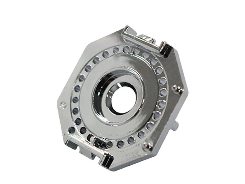
Freeze material and route before tooling
The alloy and casting route affect tool shrinkage compensation, gate and runner sizing, vent and overflow placement, cooling circuits, local inserts, ejection, machining stock and finish preparation. Changing the material after the die has been designed can invalidate these assumptions. Even where two alloys can physically run in one tool, fill pattern, solder tendency, thermal balance, dimensions, mechanical response and finish may change.
Before tool release, conduct a DFM review that identifies the proposed alloy and standard, route, machine range, cavity plan, parting line, gate, overflow, ejectors, slides, function-driving features, cosmetic zones and machining stock. The die-cast tooling guide explains the commercial and validation decisions that should accompany steel release.
Material substitution must be controlled after release. The change request should state the old and new standards and chemistries, source, melt practice, process adjustments and affected tests. Review filling, dimensions, mechanical performance, leak behavior, machining, joining and finish as applicable. A purchasing team should not accept a substitution only because both labels are described as common die-casting aluminum.
Validate the choice with representative evidence
Trial castings
Inspect every cavity intended for production. Record the tool revision, machine, cavity, alloy heat or lot, shot settings and downstream route. Check dimensions at the stage defined on the drawing. Where natural aging, machining or coating can move a feature, measure at both the diagnostic stage and final acceptance stage.
Functional and material evidence
Match evidence to failure consequence. A material certificate confirms the reported chemistry; it does not prove local soundness or finished-part strength. Dimensional studies address geometry; they do not prove leak integrity. A leak test can verify the specified pressure and medium but does not characterize every internal pore. Use complementary checks only where the risk warrants them and document sampling, test setup and acceptance.
Finish and machining evidence
Machine representative castings from each relevant cavity to the intended stock depth so subsurface issues appear before production release. Finish parts through the named pretreatment, coating, mask and cure route. Approve physical limit samples for cosmetic decisions because broad words such as "smooth" or "premium" are not measurable acceptance criteria.
Trial approval is bounded evidence. It applies to the identified tool revision, cavities, machine, alloy, settings and downstream process. A source, chemistry, die repair, machine, gate, machining depth or finish change may require partial or full revalidation according to the control plan.
Production monitoring has a different job from initial approval. Control the material identity and the process variables that were shown to matter during trials, then trend cavity-level dimensions, machining defects, leak results or finish rejects at the agreed sampling rate. A passed sample authorizes a defined route; it does not remove the need to detect drift in later lots.
Send an RFQ that allows a defensible recommendation
RFQ input | Decision it enables | Required response |
|---|---|---|
Revision-controlled 3D model and 2D drawing | Flow path, draft, tooling actions, datums and stock | Marked DFM and open assumptions |
Application, loads, temperature, environment and mass target | Alloy family, route and validation severity | Proposed standard/grade, material condition and exclusions |
Function-driving features and acceptance stage | As-cast versus CNC control and measurement plan | Datum scheme, process allocation, gauge or inspection method |
Leak, joining, heat-treatment or welding requirements | Porosity strategy and conventional HPDC suitability | Route-specific controls and representative tests |
Finish system, visible zones and limit samples | Alloy/skin compatibility, gate/ejector location and preparation | Process sequence, mask/rack points and visual criteria |
Forecast, batch pattern and program life | Cavity, tool, machine and cost scenarios | Tool assumptions, capacity basis and change-control terms |
Ask suppliers to quote the finished accepted part, not only casting weight. The response should separate tooling, casting, trimming, machining, treatment, inspection, packaging and validation assumptions. A lower alloy price can be outweighed by shorter tool life, slower machining, lower finish yield or a more demanding inspection plan. Conversely, an expensive specialty chemistry is poor value when geometry or localized machining can meet the requirement with a common alloy.
Buyer decision
Select die-cast aluminum material only after the product requirement, casting route and evidence plan agree. Use alloy tables to build a shortlist, then lock the governing standard, chemistry, condition and substitution rule. Review geometry and solidification, assign only necessary CNC features, qualify the actual finish system and release tooling after the material-dependent assumptions are documented. The winning material is the one that produces an accepted finished component through a controlled route, not the grade with the strongest isolated claim.
FAQ
- What Is the Best Die Cast Aluminum Material for Custom Parts?
- How Does Die Cast Aluminum Material Affect Part Strength and Weight?
- Does Die Cast Aluminum Material Affect CNC Machining Cost?
- How Should Buyers Choose Die Cast Aluminum Material Before Tooling?
- Can One Die Cast Aluminum Material Meet Strength, Cost, and Surface Finish Needs?