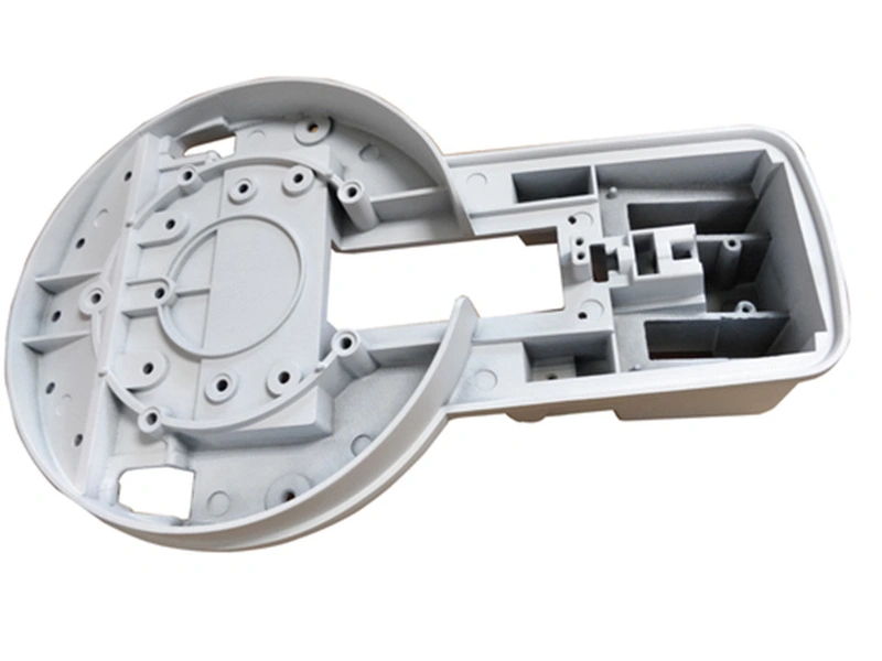
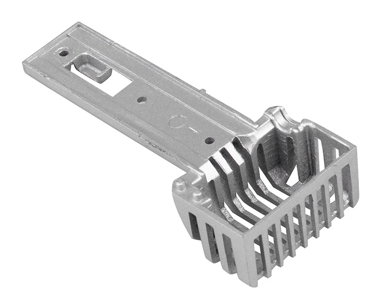
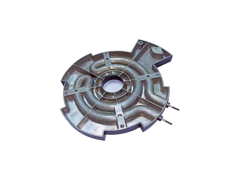
Aluminium Die Casting Service for Lightweight Custom Metal Parts
An aluminium die-casting service is a good route for a lightweight custom part when the design can be formed and released from a permanent die, demand can support tooling, and casting can consolidate useful walls, ribs, bosses or thermal features. The service should cover more than molten metal and a mold. Buyers need a controlled path through DFM, alloy and process selection, tooling, trials, local machining, finishing and inspection.
The process is not automatically right for every aluminium component. A changing design or small quantity may favor CNC machining; a large thick section may suit gravity or low-pressure casting; a demanding wrought-alloy requirement may rule out a conventional die-cast grade. The sourcing decision should start with the part's loads, environment, geometry, demand and acceptance plan, then select the manufacturing route that can produce evidence for those conditions.
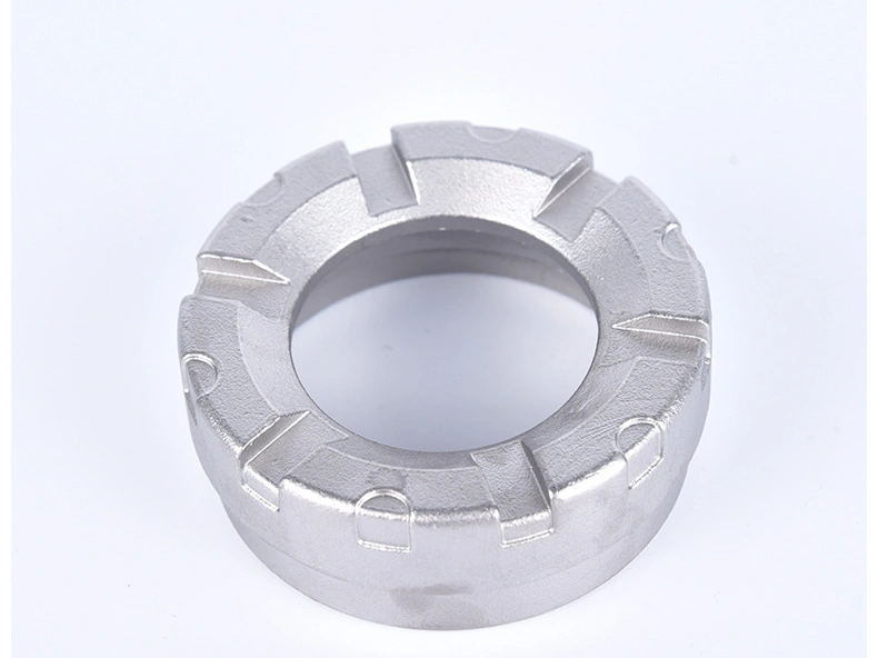
Define the part before requesting a service quote
A useful RFQ includes the controlled 3D model and 2D drawing, but also explains what the part does. Mark load paths, mounting and sealing interfaces, heat sources, prohibited leak paths, appearance zones and mating components. State the operating environment, allowable mass, alloy or performance specification, annual demand range, batch pattern, expected program life and current design maturity.
Separate casting requirements from finished-part requirements. The casting supplier needs to know which holes, threads, bores, sealing faces and datums will be machined; which surfaces remain as-cast; and which receive coating, conversion treatment or another finish. A final tolerance on a machined bore cannot be used as an unexplained requirement for the entire casting. The die-casting tolerance plan should show datum relationships and inspection stage.
Call out acceptance evidence as well. A pressure housing may need a leak test after machining. A structural bracket may need material and load validation under a named condition. A visible enclosure needs a location-specific appearance standard. Requirements such as corrosion resistance, ingress protection or mechanical strength are product-level outcomes; the relevant test, specimen, conditioning and acceptance limit must be defined by the drawing or project specification.
Confirm that die casting fits the geometry and demand
High-pressure aluminium die casting is strongest economically when a stable design uses repeatable near-net geometry across enough parts to justify the die and validation effort. Housings, covers, brackets, frames and thermal enclosures can be good candidates because shell walls, ribs, bosses and mounting features may be cast together. The tool still needs draft, a workable parting line, gate and overflow space, venting, ejection access and a trim strategy.
Geometry that traps the part in several directions may require slides or redesign. Deep narrow cores, abrupt thickness changes and long thin flow paths increase tool and process sensitivity. Large isolated masses cool differently from surrounding walls and can concentrate shrinkage. None of these observations creates a universal minimum wall or draft value; the answer depends on alloy, flow length, feature depth, die layout, machine and required surface.
Compare alternatives while requirements can still move. CNC machining has no casting die and is useful for prototypes, low demand or designs likely to change. Sand, gravity-die or low-pressure casting may fit larger sections or alloy/property routes that differ from HPDC. The decision framework in CNC machining versus casting should be applied to the projected program rather than the first sample alone.
Choose the alloy and casting route together
Aluminium is a family of alloys, not one interchangeable material. For conventional HPDC, A380, A360, A413 and A383/ADC12 are common discussion points, but the right grade follows castability, mechanical needs, corrosion exposure, thermal function, machining, finishing and supply specification. A380 is often considered for general-purpose production parts; A360 may be reviewed where its corrosion and pressure-tightness characteristics are relevant; A413 can be useful for fluidity-sensitive geometry; A383 or ADC12 may suit established commercial HPDC applications. These are selection directions, not approval of equivalence.
A356 belongs in a different conversation unless the supplier has identified the actual casting route and condition. It is widely associated with gravity or low-pressure casting and heat-treated structural applications, and it should not be inserted into a conventional HPDC quote as a casual substitute. If a drawing names A356 while the desired route is HPDC, resolve that conflict before tooling.
Suffixes, national designations and chemistry limits matter. Do not approve A383, ADC12 or another grade as interchangeable from a marketing table. Compare the controlling material standards, actual chemistry, temper or heat treatment where applicable, mechanical verification, corrosion/finish needs and regulatory constraints. The aluminium die-casting alloy comparison can frame the questions, while the released specification must settle the project.
Project question | Decision evidence | Risk if assumed |
|---|---|---|
Which casting route? | Part section, alloy condition, demand, tool concept and required properties | Quoting HPDC for a requirement tied to another casting process |
Which alloy? | Controlled designation, chemistry, environment, loads, machining and finish trials | Unapproved substitution or a finish/property mismatch |
How is low mass achieved? | Load analysis, wall/rib design, prototypes and representative casting validation | Thin geometry that cannot fill, release or carry the applied load |
Which features are machined? | Datum plan, stock, fixture concept, porosity risk and final inspection stage | Insufficient cleanup, exposed voids or unstable location |
Which finish is acceptable? | Alloy-specific coupons or parts, preparation, masking and appearance criteria | Adhesion, color, coverage or tolerance failure after casting |
When is production released? | Identified tool revision, cavities, process route and approved validation lot | Approval based on handworked or unrepresentative samples |
Design lightweight structure without creating casting risk
Weight reduction should remove material from low-value regions while preserving load paths, joining interfaces and local stiffness. A shell with appropriately placed ribs can be more efficient than a uniformly thick enclosure. Bosses need support into walls or ribs rather than isolated heavy pads. Gradual transitions and radii can improve flow, reduce abrupt thermal mass and avoid sharp tool features.
Ribs are not free reinforcement. Very deep or thin ribs may be difficult to fill and eject; heavy rib intersections can create hot spots; dense rib patterns can block spray or make trimming and cleaning awkward. Evaluate rib direction against fill, die opening, ejection and the actual load. If simulation is used, its material data and boundary assumptions must match the proposed alloy and process, then trials must verify the result.
Part consolidation can lower fastener count and assembly variation, but it can also make the die larger, add slides or combine incompatible tolerances and cosmetic zones. Compare an integrated casting with the complete alternative assembly: separate part tools, joining, fixtures, stack-up, serviceability and rejection consequence. A single casting is not automatically the lowest-risk lightweight design.
Build tooling around casting and downstream interfaces
The production die controls parting line, gates, runners, overflows, vents or vacuum, thermal circuits, slides, inserts and ejection. These choices influence air entrapment, cold flow fronts, shrinkage, distortion, flash, witness marks and cycle stability. Gate and ejector locations also affect trimming, appearance and machining fixtures. Tool design must therefore be reviewed against the finished component, not only its as-cast shape.
A machining datum should have enough stable cast support. A sealing face needs planned stock and a validation method for porosity exposed after cutting. Coated appearance areas should avoid avoidable gate scars, heavy parting mismatch and inaccessible preparation regions. The complete lifecycle in the die-cast tooling guide helps buyers define concept approval, trials, maintenance and ownership.
Tool ownership and transfer also belong in the service agreement. Native models, drawings, insert and circuit lists, machine interface, correction history and condition records may be necessary if a program moves. Ownership of the steel alone does not prove that another casting cell can run the approved process.
Treat porosity as a requirement-specific risk
HPDC fills rapidly and can entrap gas if the flow and evacuation system are unsuitable. Local solidification can also produce shrinkage-related voids. Not every internal pore has the same consequence: one away from a loaded or machined region may be acceptable under the product specification, while a connected path across a sealing wall may fail function.
Define critical regions and test the condition that matters. Radiography can show density variations under a qualified technique, sectioning can expose local structure, leak testing can evaluate a pressure boundary, and machining trials can reveal subsurface voids at functional faces. No single method proves all internal quality. Acceptance needs location, method, sensitivity and disposition rules.
When a defect occurs, correlate it with cavity number, tool revision, gate/vent condition, process data and downstream operation. Polishing or coating cannot hide a functional internal defect. Likewise, demanding "zero porosity" without a defined method is not an actionable purchasing specification.
Machine only features that need generated precision
Local CNC machining is appropriate for features whose final fit, surface or datum relationship exceeds what the as-cast route can reliably provide. Common examples include bearing seats, gasket faces, locating holes, controlled threads and mating datums. The drawing should distinguish cast pilot features from final machined geometry and state the inspection stage.
Fixture design must account for casting variation. Locating a part on a changing flash edge or weak wall can distort it during cutting. Machining stock should be sufficient for cleanup without creating an unnecessarily heavy casting. Tool access, chip evacuation, clamping and leak-test sequence should be considered before the die is released. The guide to CNC machining after die casting explains why datum and stock decisions belong upstream.
Machining can also expose porosity that was invisible as-cast. For sealing or appearance-critical cuts, validation should use representative casting and machining conditions. If a temporary sample uses extra stock, hand-selected castings or a different fixture, document that limitation.
Select finishing by alloy, function and appearance
Some aluminium die cast parts can ship after trimming, deburring and cleaning; others need conversion coating, painting, powder coating, plating, polishing, blasting or anodizing. The required finish depends on corrosion exposure, appearance, electrical behavior, wear, touch surfaces and assembly. It is incorrect to assume every part needs a decorative finish.
Die-cast alloy chemistry and surface condition affect finish response. Conventional anodizing may reveal color or texture variation on silicon- and copper-containing cast alloys and may not match the appearance of wrought aluminium. If anodizing is requested, validate the exact alloy, pretreatment, surface, color criteria and sample route. Painting and powder coating require suitable cleaning and pretreatment; masking must protect threads, electrical contacts, sealing faces and datum features.
Coating thickness can alter fit, thread engagement and grounding. Define whether dimensions apply before or after finish and where masking transitions may appear. Use the aluminium die-casting finish comparison to shortlist processes, then approve representative finished parts under project-specific criteria.
Validate the route before repeated orders
Prototype evidence must match the question. A billet-machined model can prove assembly envelope but not HPDC filling, ejection or finish response. A casting made from another alloy or temporary tool may answer selected questions while leaving production behavior open. The aluminium die-cast prototype plan should name each sample's route and limitation.
Tool trials should record revision, cavity, alloy, machine, process state and any manual intervention. Evaluate identified samples through the required trim, machining, finishing and inspection sequence. Corrections to gates, vents, inserts or cavity dimensions create a new condition; repeat the evidence affected by the change.
Production release should use a representative lot and a frozen route. Preserve approved drawings, cavity identification, inspection programs, appearance references where useful and process boundaries. During ramp, compare cavity-level dimensions, defects, machining cleanup and finish results. Stable mass production is demonstrated by controlled output, not asserted from a few favorable samples.
Evaluate the supplier as an owner of interfaces
A capable supplier should explain where responsibilities begin and end. Ask who performs DFM, tool design, casting, trim, machining, finish and final inspection; which activities are subcontracted; how drawing changes travel between them; and who owns a defect that crosses process boundaries. An integrated route is useful only when datums, masking, traceability and acceptance remain controlled.
Review evidence relevant to the part: similar process and machine range, alloy controls, tooling maintenance, cavity traceability, dimensional methods, leak or internal inspection where required, machining fixtures, finish controls and change management. Certifications or machine lists alone do not prove the proposed route can meet the drawing.
Quotation feedback is also diagnostic. A supplier should identify unresolved alloy, draft, wall transition, tolerance, finish or volume assumptions rather than silently pricing them. The buyer can use aluminium die-casting quotation checks to compare technical scope before comparing totals.
Control repeat orders and delivery condition
A released first lot is the start of supply control, not the end. Repeat purchase orders should reference the approved drawing, alloy, tool revision, cavity set, machining program, finish specification and packaging condition. Ask the supplier to notify and obtain approval for changes that can affect fit or performance, including material source, repaired tool features, casting machine, outsourced finishing, fixture revisions and inspection methods.
Packaging must protect the actual risks of a lightweight aluminium part. Thin fins and walls can bend under poorly supported stacking. Machined seal faces and bores may need caps, separators or corrosion-conscious cleaning and handling. Coated cosmetic surfaces need contact and abrasion control. Define cleanliness and preservation for fluid, electronic or adhesive-bonded assemblies instead of assuming a visually clean carton means the part is ready to use.
Incoming inspection should confirm identity and condition while production evidence remains with the supplier. Agree lot and cavity traceability, nonconformance containment, rework authorization and retained samples where appropriate. When a dimensional or finish trend moves, review the tool and process history before widening acceptance. This discipline keeps cost reduction from quietly turning into specification drift.
Any requested departure from the approved alloy, die, machine or downstream route should be submitted before shipment with its reason, affected requirements and proposed revalidation. Silence is not change approval.
RFQ inputs and project boundaries
Send the controlled CAD and drawing, alloy specification or performance needs, service environment, expected loads, target mass, annual/lifetime demand range, batch pattern and launch state. Mark cast versus machined features, datums, critical characteristics, sealing regions, appearance zones, finish, masking, assembly and packaging requirements.
State the desired deliverables: DFM and tool-concept review, simulation where justified, tooling and trim scope, trial quantity by cavity, dimensional report, material records, internal-quality or leak tests, machining and finish validation, appearance samples, production control plan and change-approval method. Define tool/data ownership, included corrections, spare inserts, storage, maintenance reporting and transfer condition.
Do not request unconditional guarantees for tolerance, properties, lead time or annual capacity before geometry, route and validation are reviewed. Ask suppliers to list assumptions and exceptions. A sound service proposal makes the boundary between as-cast capability, secondary operations and finished-part acceptance visible.
Buyer decision
Choose an aluminium die-casting service when the released product and demand justify permanent tooling and when near-net casting can create useful lightweight geometry. Approve the alloy together with the casting route, design the tool around machining and finishing interfaces, and validate the complete finished-part path. The best supplier is the one that turns those dependencies into traceable decisions and evidence, not the one that gives the broadest promises from an incomplete RFQ.
FAQ
- What Is Aluminium Die Casting and When Should Buyers Use It?
- Which Aluminium Alloys Are Best for Die Casting Parts?
- Is Aluminium Die Casting Better Than CNC Machining for Custom Parts?
- Do Aluminium Die Cast Parts Need CNC Machining and Surface Finishing?
- How Can Buyers Reduce Cost in Aluminium Die Casting Projects?