ADC12 Enclosure Walls: 2.5 mm, Ribs and Shielding
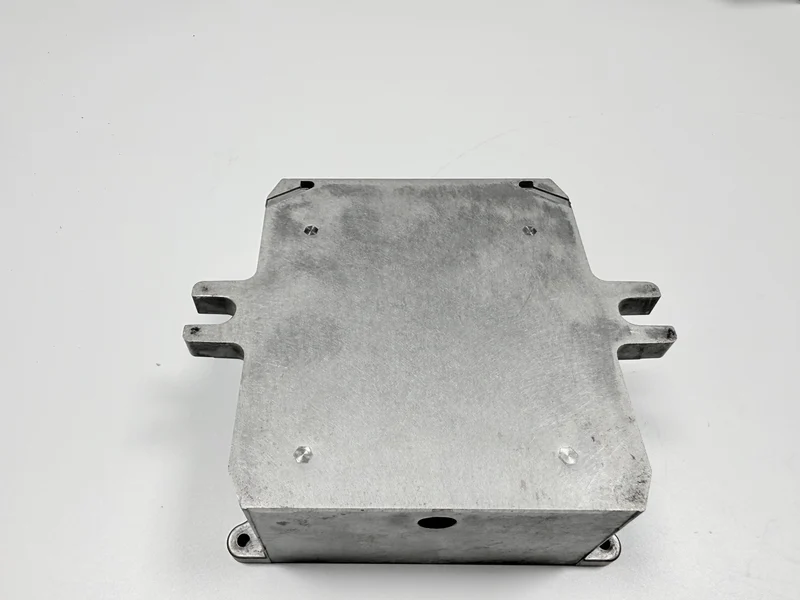
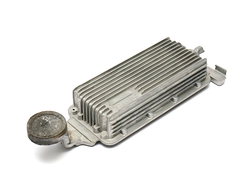
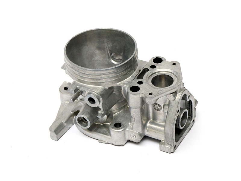
ADC12 suits this enclosure because the grade fills a 2.5 mm wall before the section sets. Silicon carries the fluidity, copper the hardness, and iron keeps the melt from soldering to the die. The aluminium HPDC route casts a 120 × 90 × 45 mm body at 380 ± 30 g.
The drawing is not released, so every figure below falls into one of three classes: a drawing target from the estimate, a table specification from the surface data, or a typical value from the process window. The table marks the class of each row.
Why does ADC12 suit a 2.5 mm enclosure wall?
ADC12 suits the wall because its silicon does the filling. It lowers the melting range, so the metal reaches the far wall before it stiffens, and a leaner grade would short-shot the last corner.
ADC12 is a JIS grade, and ASTM B85 carries the equivalent 383 chemistry. The standard sets a minimum and a maximum for each element, which makes the grade a window: two heats can pass from opposite ends and behave differently in a 2.5 mm section.
The elements split the work. Silicon buys the fluidity, copper buys hardness and costs ductility, and iron keeps soldering in check while forming platelets that dull a tap. Magnesium is a capped residual rather than a strength lever, and zinc, lead and tin sit under limits, with tin opening hot shortness on a thin wall. The certificate carries those limits, so a heat runs softer or harder with where its silicon and copper land.
| Requirement | Target | Allowed range | Basis |
|---|---|---|---|
| Wall thickness | 2.5 mm | 2.5 ± 0.2 mm | Drawing target |
| Rib thickness | 2.0 mm | As drawn | Drawing target |
| Finished weight | 380 g | 380 ± 30 g | Drawing target |
| Opening face flatness | 0.10 mm | Not over 0.10 mm | Drawing target |
| Temper | As-cast F | F only | Drawing target |
| Melt temperature | 650–680 °C | Typical band | Typical |
| Cavity film | 0.3–1.0 µm | Inside that band | Table spec |
| Contact resistance | 2.5 mΩ | Not over 2.5 mΩ | Table spec |
What does the as-cast F temper mean for a machined box?
F temper removes one source of movement, the heat treatment. Ejection, clamping and the cut still move the box, so the 0.10 mm face depends on where the ejector pins push, how the mill clamps, and the last finish pass. The opening face page works through both causes.
T5 would add a controlled cool and an age, and T6 a solution treatment and a water quench before the age. A T6 part goes out as its own route, validated on its own drawing and judged after the quench, and this drawing stays F. The quench also opens blisters where porosity sits under the skin, so the check comes after the heat treatment, not before.
Stock on the two cut faces is pending foundry sign-off, because it follows how far the free part moves between setups. The post machining scope carries that allowance, and one set too thin turns a bowed face into a scrapped casting.
Why does ASTM B85 matter when the drawing says ADC12?
A sheet that carries only ADC12 leaves the element limits and the sampling open, and two suppliers can ship different metal under one word. The specification should call the grade, the standard and the temper on one line, and the UNS number belongs on the certificate that arrives with the first production heat.
A spectrographic reading per heat turns the window into a figure that can be held against the target drawing, and an ADC12 high-pressure project runs on the grade in production.
How much does a 2.0 mm rib add to 380 g?
The ribs are already inside the 380 ± 30 g target, and CAD confirms single-part weight before the die, and the first article goes on a scale. At 2.0 mm they buy stiffness without a second wall.
A rib at 2.0 mm against a 2.5 mm wall is close to the section it stiffens, so the junction is a hot spot that freezes after the wall. The sink that can follow is a thickness question, which the rib root page takes up.
Why does a thin wall need a 650–680 °C melt?
The melt runs at 650–680 °C, a typical band, because a 2.5 mm section sheds heat to the die faster than a thick one. Below the band the front of the metal sets before the far wall fills, and the result is a cold shut or a short shot at the last corner. The wall thickness starting point sets out that balance from the other end.
Above it the alloy picks up hydrogen and the cycle runs beyond 75 s, the top of the 55–75 s cycle band. The process blog carries the rest of the window, from die heat to intensification pressure and the full cycle time.
Why does a 2.5 mm wall want a 200–230 °C die?
The die runs at 200–230 °C, a typical band that slows the chill so a 2.5 mm wall fills. A cold die pulls heat from the first metal it touches, and that skin can drag or cold-shut before the cavity fills.
Soldering is the other failure, and it comes from a die that runs too hot where the gate feeds, not from a cold one. The tool is drawn as a one-cavity H13 die with a design life, and the cavity count, the steel and the life all wait on a foundry sign-off.
What does 70–90 MPa shot pressure do to the wall?
Intensification takes the shot to 70–90 MPa, a typical band, and that pressure packs the 2.5 mm section before the gate freezes. Pressure works through the gate, so a wall far from it sees less of the figure than the sprue does.
Pressure does not close porosity. Gas trapped in the shot stays where it is, and a hot spot that freezes without feed leaves shrink behind. Porosity can open on a cut face, so the allowance and any mapping are drawing calls pending foundry sign-off; a cut face near it is worth mapping first, before the stock is fixed.
How does conductive oxidation shield the cavity?
The aluminium housing is the shield, and the film keeps the faces that must stay conductive. Conductive oxidation puts a 0.3–1.0 µm film on the cavity to MIL-DTL-5541 Type II, and the acceptance is 2.5 mΩ of contact resistance or less. The line and the measured value stay open until the foundry signs off.
The two surfaces split by face. Powder at 60–80 µm covers the outside, conductive oxidation covers the cavity, and the mating faces are masked so the two meet at a named edge, which the conductive coatings page sets out.
The film is a material decision because it grows out of the surface. A conversion film reacts with the aluminium it meets, so a machined face and a cast skin take it at different rates, and the drawing has to name the faces that carry it.
Why is the alloy fixed before the coating is chosen?
Alloy and temper come first because the two surface routes do not sit on every grade alike. A conversion film needs a surface that reacts evenly, and a powder needs a skin that takes a charge without outgassing the porosity under it.
Copper ties the two decisions together. The copper that buys hardness also leaves the surface less even for a conversion film and shifts the colour of an anodic finish, so a part that must be anodised for appearance is a different material question. The aluminium alloys index is where that comparison starts.
Why is salt spray not specified for this enclosure?
Salt spray does not appear in the specification because the box serves indoor equipment, with no outdoor exposure claimed. A salt-spray hour count would buy a different surface and a different route.
The same boundary decides when ADC12 is the wrong pick. Outdoor exposure, a decorative anodic finish, a section too thin for the die to fill, or a part that has to hold a pressure test each move the work off this grade and this route.
Inside the boundary the part is a 120 × 90 × 45 mm box at 380 ± 30 g, with a flat opening face, an M3 boss pattern and a cavity that conducts to ground.
What should a buyer confirm about ADC12 before release?
Confirm three items before release: the grade and temper on the certificate, the element limits on the same certificate, and which faces take which surface.
FAQ