Aluminium HPDC Enclosure: 2.5 mm Walls, 0.10 mm Flatness
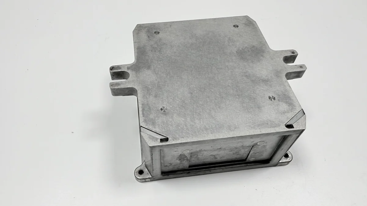
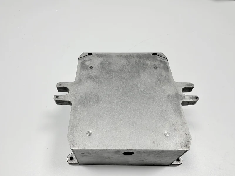
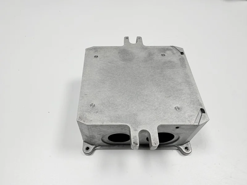
An aluminium HPDC enclosure for a 120 by 90 mm control box turns on two faces: the opening the lid closes on and the top face the board sits under. The aluminium HPDC option casts 2.5 mm walls, 2.0 mm ribs and the M3 bosses in one shot, then mills the opening face flat and masks the mating faces before coating.
The box measures 120×90×45 mm and weighs 380±30 g, with the opening face held to 0.10 mm and the M3 boss positions within Ø0.2 mm. Every figure is a drawing target, and the alloy is quoted as ADC12 to ASTM B85 in the as-cast F temper.
What does HPDC replace on a 120 by 90 mm box?
Die-cast aluminium replaces a folded steel box or an extruded profile closed with end caps, and the swap moves work between the press and the bench. A folded box needs no die, but a seam runs along every corner.
At 120 by 90 by 45 mm with a 2.5 mm wall, the die carries the shape in one shot and the bench carries the two milled faces, the tapped bosses and the coating steps. The wall figure closes first, and the wall thickness starting point argues the same case from the other end.
A folded box spends its money on labour; the cast box spends it on a die cut once, and a small order meets that cost before it meets the metal.
Which dimensions are locked before the die is cut?
Five features close before the die is cut, because a change after the cut is die work. Two are limits and three are nominals, and the table separates them.
| Feature | Target | Allowed range | Set by |
|---|---|---|---|
| Opening face flatness | 0.10 mm max | Not over 0.10 mm | Die and the finishing pass |
| Outline at the opening | 120 × 90 mm | ± 0.3 mm | Die and the opening cut |
| Wall thickness | 2.5 mm | 2.5 ± 0.2 mm | Die and gate |
| Rib thickness | 2.0 mm | No tolerance stated | Die |
| M3 boss position | Ø0.2 mm max | Not over Ø0.2 mm | Die, then the tap |
Where ribs, windows and bosses meet, the wall features decide which of the five move as one.
Why is the opening face the datum for the top cut?
The opening face is the datum because the lid closes on it and the board hangs from bosses that stand off it, so every other cut has a face to measure from.
One pass cannot finish both faces and hold that datum, so the process chain runs as two: rough the opening face to establish the datum, mill the top face from it, stress relief, then finish the opening face. That order is a hypothesis pending foundry sign-off.
A datum taken from the top face reverses the two passes. Setting the datum on the opening face costs one decision at the drawing stage; moving it later costs a second setup on every box.
How do 2.5 mm walls fill around 2.0 mm ribs?
On this die design the gate is laid out at the floor's thick section, pending foundry sign-off, so metal enters at the floor, crosses it and climbs the 2.5 mm walls from the inside. The 2.0 mm ribs draw from the wall they meet, and the rib root furthest from the gate fills last.
Melt at 650–680 °C and a die at 200–230 °C are the typical window, and it is narrow because the wall sets before the ribs do. Drop the melt and the wall can cold-shut before the ribs fill; raise it and the roots need more feed than the gate can pass.
A rib root is a hot spot in a part with no thick section anywhere else. The rib root page answers sink marks on that face.
Where does the melt window sit for a thin box?
The window sits in three places rather than one value: intensification raises shot pressure to 70–90 MPa after the shot, the cycle runs 55–75 s, and the overflows sit at the four corners. Pressure works through the gate at the floor, so a wall far from it sees less.
The cycle keeps the die at temperature between shots, and the four corner overflows take the cold front before it reaches a rib root. Pressure and cycle are typical; the overflow layout is a drawing target.
Because the cycle sits at 55–75 s, press time is a block in the quote, and a longer cycle raises the cost of every shot.
Which faces are machined after casting?
Machining covers two faces and one set of holes: the opening face, the top face and the M3 bosses. Cast faces keep the die finish.
The chain runs through casting, degating, vibratory finishing, milling the opening and top faces, tapping, cleaning, coating with the mating faces masked, and final inspection. Eight steps, and the mill and the tap are the two that change a dimension.
Two faces milled in two setups is two stations, so the machining block of a quote splits there. Where windows and bosses sit against those faces is set out in which features need milling.
Why are the M3 bosses tapped after machining?
Tapping comes after milling because the tap has to follow the datum the mill has just cut. Tap first and the thread sits where the casting put it, so boss and face disagree by whatever the mill took off.
A thread cut into a porous as-cast boss can strip at assembly, and a stripped thread scraps a box that already carries both milled faces.
The release criteria for that thread sit on the thread-stripping page in the FAQ list below.
Why is the mating face masked before coating?
The mating faces carry a mask because a 60–80 µm film between two faces that have to meet holds the lid off its seat.
Masking is a drawing item rather than a consumable. The mask drawing names the opening face, the boss tops and every M3 bore, and how that list is built by bore rather than by area is set out on the masking page.
The box takes two surfaces on different faces: powder at 60–80 µm outside, and conductive oxidation at 0.3–1.0 µm to MIL-DTL-5541 Type II in the cavity where a ground path is needed, and the conductive coatings page covers that film. The 60–80 µm powder and the cross-cut test apply to the powder finish; the conductive finish goes out on thickness and on 2.5 mΩ of contact resistance or less.
How is the 0.10 mm opening face released?
A surface plate and a 0.10 mm feeler gauge release the opening face: the face rests on the plate and the blade must not enter around the frame. The reading comes from a free part, because a face measured in the fixture reads to the fixture.
The finish pass comes last in the two-pass order, after the stress relief if the route includes one. An example record found six of 200 parts at 0.15 mm, and the recheck after the process change read 0.06 mm.
Why a face moves under ejection and clamping belongs to the opening face page, which uses the same plate check.
Which gauges release a coated enclosure?
Six checks release a coated box. The opening face goes on a plate with a feeler gauge, the boss positions go on a CMM, and the table below carries the other four.
| Check | Spec | Acceptance rule | Gauge |
|---|---|---|---|
| Thread M3 | M3 | Go gauge passes, no-go does not | Go/no-go gauge |
| Proof torque | 2.5 N·m | Holds without turning | Torque wrench |
| Coat thickness, powder finish | 60–80 µm | Within the band | Magnetic film gauge |
| Coating adhesion, powder finish | ISO 2409 ≤1, class 1 or better | Class 0 or 1 | Cross-cut tool |
| Appearance face | None visible at 300 mm | Any visible mark fails | D65 lamp |
Bench time follows the six checks, and the plate and the D65 lamp decide most arguments because both judge a face no other gauge sees. A coat that peels at the cross-cut fails whatever the film gauge reads, so both readings go on one report.
When is a folded or extruded box the better buy?
A folded box wins when the order is too small to pay off a die, and when shielding is not the deciding function. An extrusion wins when the section stays constant and the ends close with caps, because its tool costs less than a die.
HPDC wins when one part has to carry bosses, windows and a flat opening, and when the order runs long enough to spread the die.
Casting and machining on one order run as one chain, as in an aluminium shell cover case.
This box serves indoor equipment, and the drawing claims no outdoor or salt-spray exposure. Ask for the wall, the boss positions and the opening face as three separate lines before choosing a process.
What does an HPDC enclosure quote contain?
Four blocks cover the eight steps, and the die carries all of them without being one. Casting with degating and vibratory finishing takes steps one to three, the two milled faces with the tap take steps four and five, and cleaning, the mask, the coat and the release checks take steps six to eight.
On a 380 g box, material is one input of four, and a price built on weight misses the die, the two milling passes, the masking and the release checks.
The die is a single cavity in H13 with a design life of 150,000 shots, and that cost does not move with the order, so a short run carries a large share on each box. Stress relief, where the chain carries it, adds a furnace slot between the two milling passes and lands in the third block.
Four items wait on the foundry: the ADC12 grade, the die layout and its design life, the stress relief and the surface finish.
Send the drawing with the five locked features, the chosen surface and the mask list, and check the opening face and the thread on the first article.
FAQ
What should a buyer ask before quoting an enclosure?
Lock the five features before the die is cut, then fix the surface finish and the mask list before the first coated part.