Complex Geometries? Sand Casting Makes It Possible
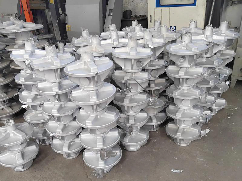
Why Sand Casting Is Ideal for Complex Shapes
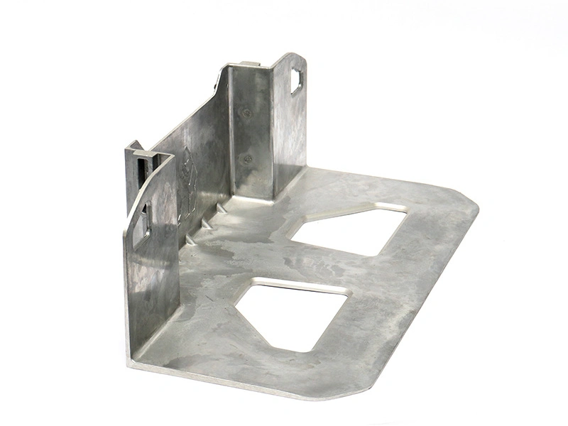
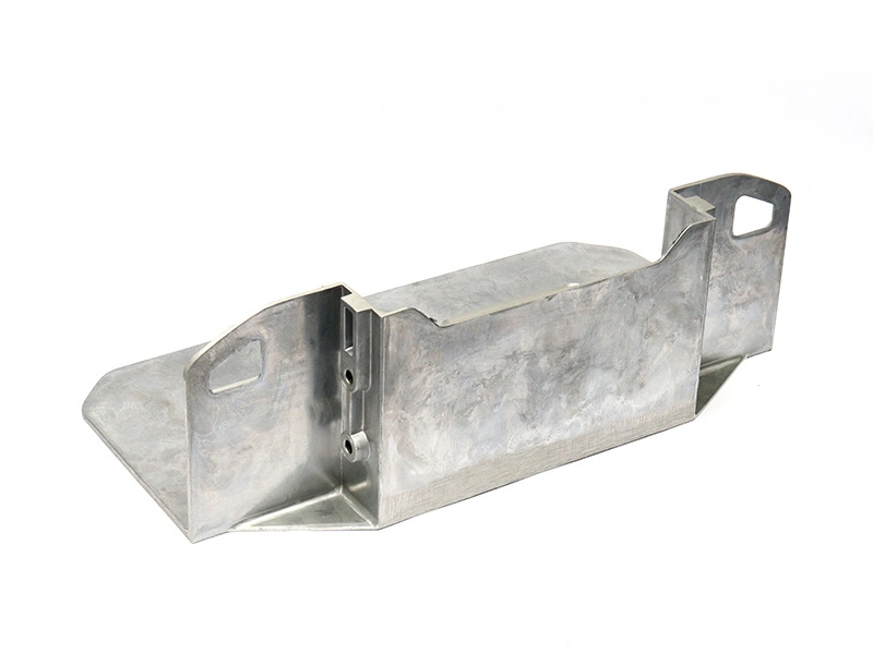
As an engineer at Neway, I often work with components whose contours, cavities, and internal passages would be nearly impossible—or prohibitively expensive—to manufacture using permanent molds or subtractive machining alone. Sand casting solves this challenge through the natural flexibility of its mold material. Since sand molds are created using compacted sand rather than hardened steel, they adapt naturally to intricate shapes, undercuts, and three-dimensional features without requiring high-cost tooling or complex multi-slide die structures.
For many early-stage programs, sand casting is the most cost-efficient option when handling highly contoured housings, large structural forms, heat-dissipation geometries, or prototypes that require fast modifications. Using sand casting enables us to produce these parts quickly, providing engineering teams with real metal samples that accurately represent future production behavior.
Permanent-mold processes typically demand significant upfront investment, and machining deep or organic forms can be slow and expensive. By contrast, sand casting offers design freedom at a manageable cost, making it ideal for prototypes, low-volume production, and structural parts where geometric complexity is essential.
Understanding How Sand Molds Support Design Freedom
The core advantage of sand casting lies in its ability to form multi-sectional, removable molds that accommodate design elements traditional processes struggle with. Internal channels, rib networks, deep cavities, and multi-surface contours can all be created by arranging sand cores in place before pouring.
This design freedom is especially beneficial when the project begins with digital development tools or physical mockups. When early models require mechanical validation, engineers sometimes use rapid prototyping to refine shapes before committing to castable designs.
Sand molds also eliminate many of the geometric restrictions typically associated with high-pressure die casting. Undercuts, non-uniform walls, and integrated assembly features can be cast with less concern for die-release conditions. Sand casting even outperforms die casting for very large parts or shapes that extend beyond machine tonnage limits.
When geometric complexity drives manufacturing decisions, engineers often pair sand casting with downstream processes, such as CNC machining, to meet final tolerance requirements. This hybrid approach enables complex cast forms to achieve high precision without compromising design intent.
Material Capabilities Behind Complex Sand-Cast Forms
The versatility of sand casting extends to its broad alloy compatibility. Aluminum is among the most commonly used materials for complex castings due to its excellent castability and weight advantages. When selecting an alloy, engineers often reference aluminum alloys to compare mechanical strength, corrosion performance, and thermal behavior.
For applications demanding higher hardness or load-bearing capability, zinc alloys may be appropriate. Designers evaluating prototypes or functional parts frequently consider zinc alloys for their dimensional stability and good flow characteristics.
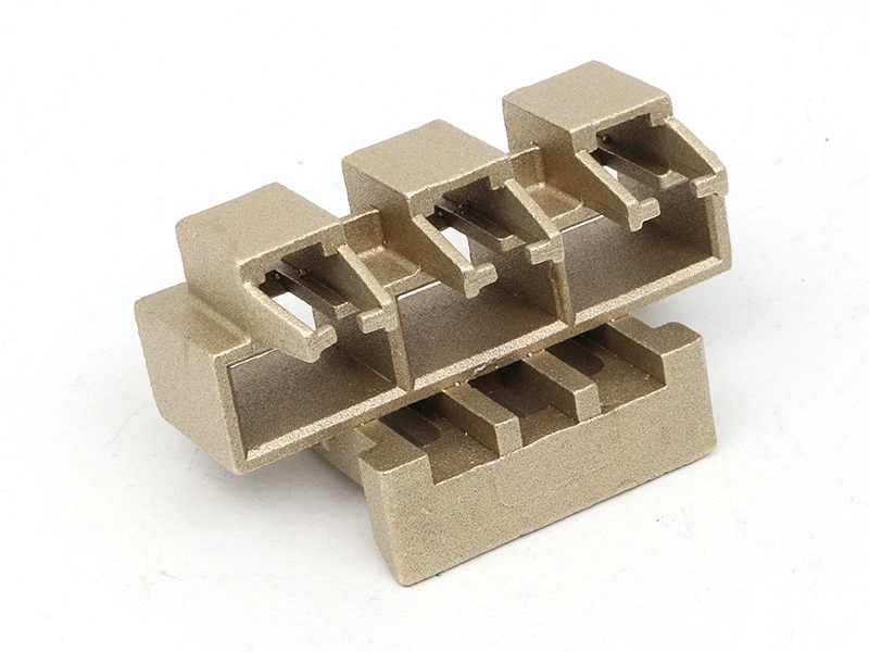
Copper and brass alloys are also cast using sand molds, particularly for parts that require corrosion resistance, conductivity, or thermal reliability. Options such as copper brass alloys support a wide range of technical requirements in automotive, energy, and industrial equipment.
In cases where prototype tooling or heat-resistant components require alternative materials, engineers may explore tool materials to compare performance differences during pre-production trials.
The adaptability of sand molds to nearly any castable alloy allows engineers to balance geometric ambitions with functional demands, ensuring prototype and production components reflect real-world application performance.
Engineering Techniques That Enable High-Detail Castings
Achieving complex geometry in sand casting relies not only on the mold material but also on the techniques used to create it. Core design is a central element. Multi-part cores can form intricate passages, enclosed sections, or spatially complex voids that traditional machining cannot economically achieve.
Draft angles, gating placement, and wall thickness distribution must be carefully engineered to maintain casting quality. When dealing with highly detailed structures, teams may begin by generating an additive model using 3D printing, then converting this model into cast-ready tooling or trial molds.
Rapid tooling paths allow quick production of core boxes or mold impressions using additive or CNC-cut patterns. For applications requiring non-metal validation tests before casting, teams may create early-stage geometry using urethane casting.
Digital simulation and specialized gating design ensure that molten metal flows effectively into all critical features. These techniques reduce porosity, improve structural integrity, and ensure even complex shapes meet dimensional targets.
When Sand Casting Delivers Advantages Over CNC and 3D Printing
Sand casting is not always the fastest or most precise method available, but it excels where size, shape, or wall thickness makes CNC or additive manufacturing impractical. Very large housings, thick-walled structures, and parts with broad geometric envelopes are often too costly to machine from billet. In such cases, sand casting drastically reduces raw material waste and machining time.
Additive manufacturing is ideal for small or intricate components but becomes limited when parts exceed build volume, require high thermal mass, or demand production-ready alloys not available in common printing formats. For these scenarios, sand casting remains a competitive and scalable option.
When parts require final accuracy beyond what casting alone can deliver, secondary operations such as die castings post machining bring the geometry within tolerance. Surface treatments and cleaning steps—similar to post-processing approaches for die castings—further refine the final part. This hybrid workflow offers an efficient balance between complexity, cost, and manufacturability.
Post-Processing Approaches for Complex Cast Shapes
Complex castings often require targeted machining to achieve flatness, precise holes, or sealing surfaces. Machining strategies must accommodate irregular geometries and casting variation, and our engineering team works closely with customers to define which surfaces require finishing.
Blasting, trimming, and finishing steps help remove residual sand, mold seams, and minor surface irregularities. Inspection methods, such as CMM measurement, X-ray imaging, and section analysis, help validate internal structures that cannot be visually inspected.
By integrating flexible mold design, reasonable tolerance expectations, and thoughtful post-processing, even highly detailed forms can be produced reliably and repeatedly.
Industries Leveraging Complex Sand-Cast Geometries
The industries that benefit most from complex sand castings are those that balance structural demands, thermal performance, and the speed of development. Automotive engineering relies heavily on sand casting for housings, engine components, and structural brackets. Collaboration examples involving automotive components demonstrate how sand casting accelerates design validation.
Aerospace programs regularly evaluate high-strength, lightweight sand-cast structures. These prototypes often support aerospace parts development and offer an efficient path to test assemblies before committing to more advanced casting or machining routes.
Consumer electronics benefit from early prototypes that require quick iteration cycles while still maintaining functional mechanical performance. Projects involving consumer electronics hardware demonstrate how quickly sand-cast housings can support thermal tests and structural evaluations before mass production.
Across all industries, sand casting supports the fabrication of structural frames, heat-dissipation components, ergonomic shapes, and large-scale mechanical assemblies. Its geometric freedom makes it one of the most versatile processes available for R&D and pre-production.
Selecting the Right Partner for Intricate Sand-Casting Projects
Success in complex sand casting depends heavily on engineering expertise. Selecting a supplier capable of designing molds, configuring cores, selecting materials, and performing post-processing ensures prototype accuracy and repeatability. A partner offering comprehensive engineering guidance—such as Neway’s design and engineering service—helps refine part geometry, minimize defects, and streamline the transition from prototype to production.
Consistency across batches is crucial, especially in pilot runs. Reliable process control, alloy management, and machining capacity enable sand-cast parts to match design intent even when complex geometry is involved.
With flexible tooling approaches, broad material choice, and engineering-driven optimization, sand casting remains one of the most powerful processes for translating complex designs into manufacturable parts.
FAQs