How Prototype Sand Casting Helps Buyers Validate Custom Metal Parts Before Production
How Prototype Sand Casting Helps Buyers Validate Custom Metal Parts Before Production
Prototype sand casting helps buyers test a real cast metal route before committing to higher-volume production tooling, machining fixtures or finished-part approval. It is useful when a project needs a metal prototype that reflects casting behavior, not only a shape made from billet, plastic or printed material.
The buying question is practical: will this part cast, machine, finish, assemble and survive the next production stage? A prototype sand casting can answer that question by showing how the selected alloy fills the mold, how the pattern and cores control internal geometry, whether the wall thickness is stable, how much machining allowance is needed and which dimensions must be controlled after casting.
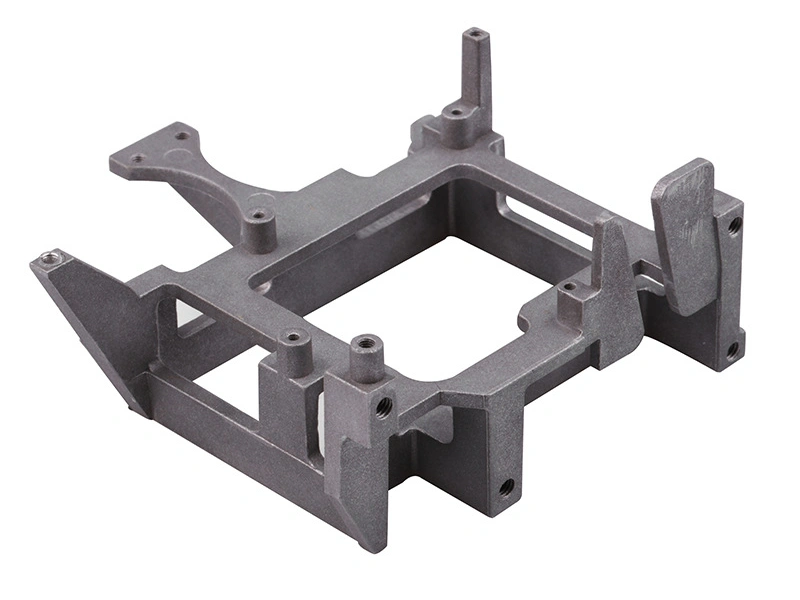
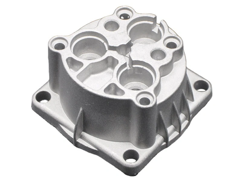
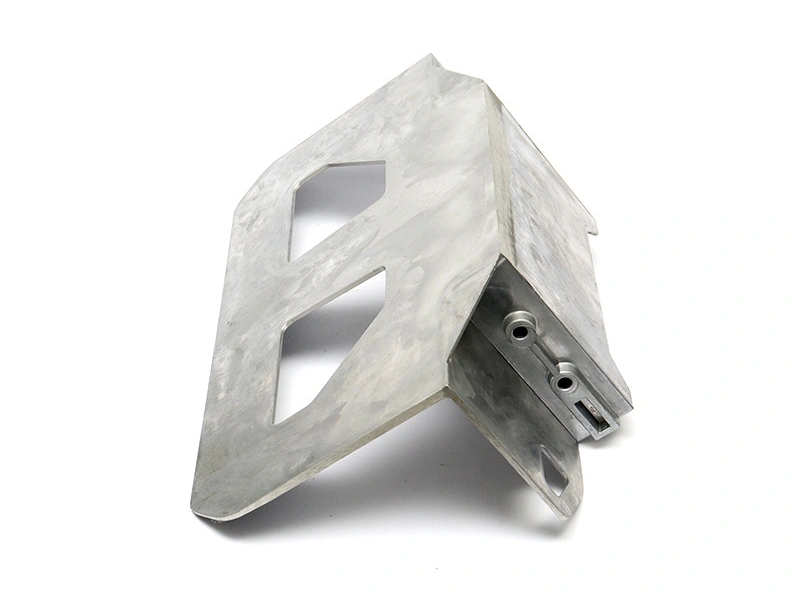
This process is often used for pump housings, motor housings, valve bodies, brackets, covers, impellers, gearbox housings, hydraulic components, industrial frames and custom cast metal parts that need early validation. The prototype is not only a sample for appearance. It should produce engineering evidence that helps the buyer decide whether to revise the drawing, change material, adjust machining scope, approve a small batch or move toward repeat production.
Buyers comparing prototype routes can also review rapid sand casting for fast prototypes, cost-effective sand casting for small batches, complex sand cast geometry planning, sand casting material choices, sand casting compared with CNC machining and 3D printing and materials for low-volume sand casting before locking the prototype plan.

What a Prototype Sand Casting Should Prove
A useful prototype sand casting should prove more than whether a foundry can pour one part. It should prove whether the design can become a manufacturable casting with controlled material, repeatable geometry, realistic post-machining and acceptable risk. Buyers should treat the prototype stage as a decision checkpoint, not as a loose sample order.
The first proof point is castability. Thin walls, deep pockets, heavy bosses, isolated ribs and sudden section changes can create cold shut, shrinkage, porosity, hot spots or distortion. A prototype casting lets the supplier and buyer see whether the drawing needs radius changes, wall adjustments, feed changes or core design changes before production tooling absorbs those mistakes.
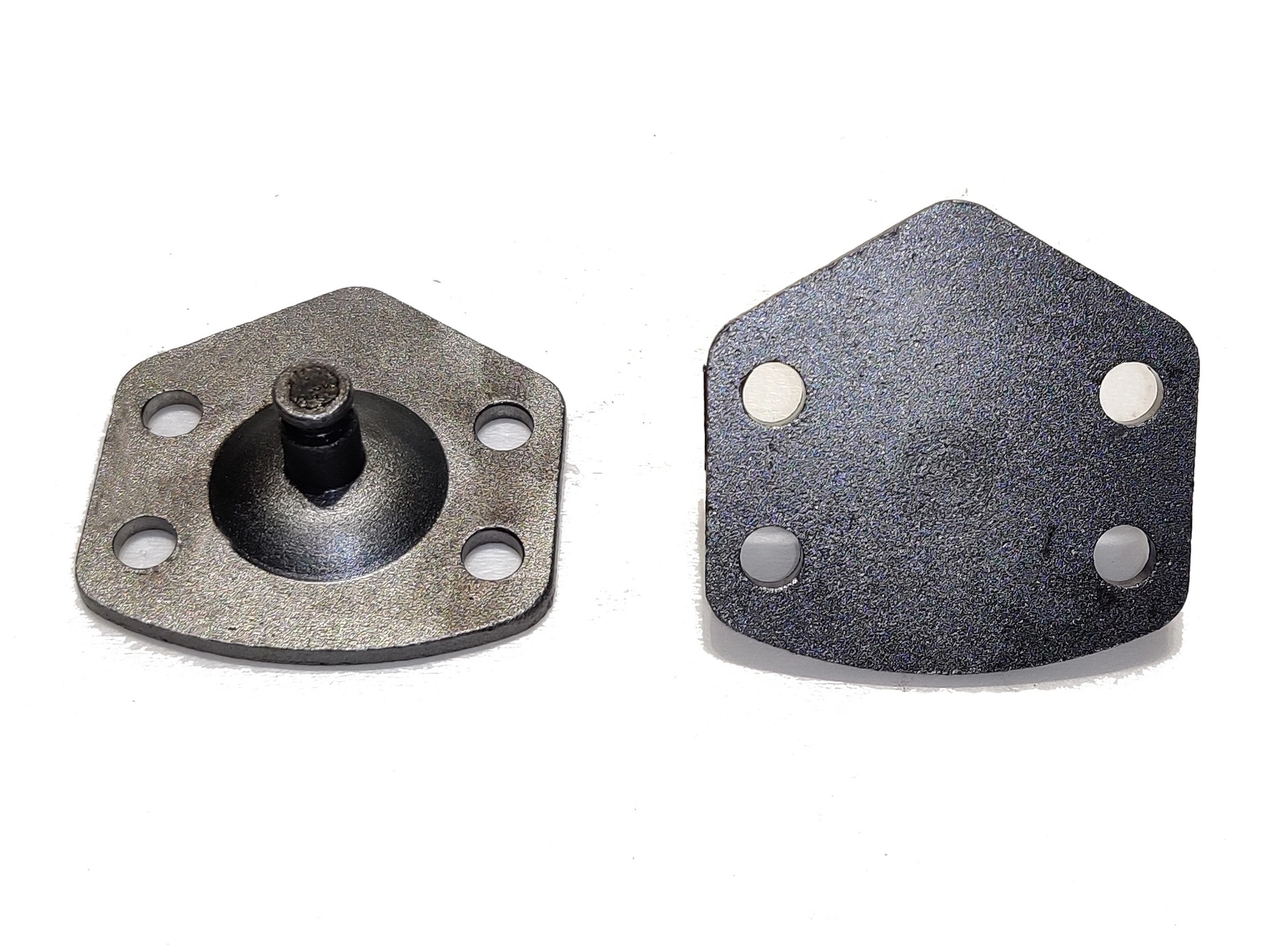
The second proof point is functional geometry. Many sand cast prototypes still need CNC machining on sealing faces, bearing bores, threaded holes, datum pads, mounting surfaces and assembly interfaces. The casting should leave enough stock for machining but not so much that every surface becomes expensive to finish. The prototype should confirm which surfaces can stay as-cast and which surfaces must be machined.
Validation Item | What the Prototype Should Confirm | Buyer Decision |
|---|---|---|
Castability | Wall thickness, ribs, bosses, transitions, metal flow and shrinkage risk | Revise geometry before production tooling if casting defects appear |
Pattern and core logic | Parting line, core support, draft, core shift risk and mold handling | Confirm whether the internal geometry is realistic for sand casting |
Material behavior | Strength direction, porosity tendency, heat treatment response and machinability | Keep the alloy or compare a second material route |
Machining allowance | Stock left on holes, faces, bores, pads and datum surfaces | Define CNC scope before quoting the next batch |
Tolerance feasibility | Which dimensions can stay cast and which need machining | Set realistic drawing tolerances for the production route |
Surface condition | As-cast texture, parting line marks, riser removal, finishing needs and coating risk | Approve finishing direction or change cosmetic requirements |
Assembly fit | Interface dimensions, sealing surfaces, threaded features and mating part alignment | Release a pilot batch only after fit issues are resolved |
When Prototype Sand Casting Is Better Than CNC Machining
Prototype sand casting is better than CNC machining when the buyer needs to validate a casting route instead of only checking the shape of a part. CNC machining is excellent for precise prototypes, but it removes material from solid stock. It does not reveal feeding behavior, shrinkage, core movement, casting texture, riser removal, heat-treatment distortion or the real amount of machining stock needed after a casting is poured.
For a bulky housing, cover, pump body or bracket, machining the whole part from billet may create a beautiful prototype that hides future casting risk. The buyer may approve the shape, but later discover that production castings have porosity near bosses, unstable wall sections, internal core shift or insufficient stock on the sealing face. Prototype sand casting reduces this gap because the prototype is made by a casting process from the beginning.
CNC machining may still be the better first route when the design is changing every week, the part is small, the quantity is one or two pieces, the material must be billet-grade, or every critical feature needs tight tolerance immediately. The choice should depend on what the prototype must prove.
Prototype Route | Best For | Main Limitation |
|---|---|---|
Prototype sand casting | Validating castability, material route, machining allowance and production transfer | Requires pattern planning and has wider as-cast tolerance than CNC |
CNC machining from billet | Fast precision prototypes, tight functional dimensions and frequent design changes | Does not prove casting defects, core behavior or foundry process risk |
3D printed model | Form, fit, ergonomics and visual review before metal work | Does not prove metal material, machining, heat treatment or casting behavior |
Investment casting prototype | Smaller detailed parts with fine surface and complex features | May not match sand casting economics or large-part process route |
Material Choices for Prototype Sand Casting
Material selection is one of the main reasons buyers use prototype sand casting. The prototype can show whether the chosen alloy provides the right balance of strength, weight, machinability, corrosion resistance, heat treatment response and cost. For aluminum parts, common discussion points include A356-T6, 319 aluminum and other casting alloys. For heavier-duty parts, ductile iron 65-45-12, gray iron, carbon steel castings, bronze alloys or 304 stainless steel may be considered depending on load, wear, corrosion and temperature.
Buyers should not ask for material selection only by naming a broad family such as aluminum, iron or steel. The supplier needs to understand the application, load direction, working temperature, fluid contact, sealing requirement, surface finishing, machining needs and production quantity. A pump housing may need corrosion resistance and leak control. A bracket may need stiffness and dimensional stability. A valve body may need pressure integrity and clean machined seats. These requirements change the material route.
Prototype sand casting is especially useful when the buyer is not sure whether a material choice will machine cleanly or hold the required surface after casting. A356-T6 may be attractive for structural aluminum castings, but it must be planned differently from high pressure die casting alloys such as A380 or ADC12. Ductile iron may be better for strength and wear, but machining allowance, weight and finishing need to be reviewed. Stainless steel cast prototypes can validate corrosion resistance but usually require more careful machining and cost control.
Material Direction | Typical Prototype Use | Buyer Should Confirm |
|---|---|---|
A356-T6 aluminum | Structural housings, brackets and lightweight cast parts | Heat treatment, machining stock, porosity limits and surface finish |
319 aluminum | General aluminum cast components requiring castability and machinability | Strength target, thermal behavior and post-machining scope |
Ductile iron 65-45-12 | Load-bearing parts, brackets, housings and wear-related components | Weight, machining allowance, coating and impact requirements |
Gray iron | Machine bases, covers and vibration-damping components | Strength class, surface protection and machined datum locations |
304 stainless steel | Corrosion-resistant prototypes and process equipment parts | Casting cost, machining difficulty and final surface requirement |
Bronze alloys | Bushings, wear surfaces, marine parts and bearing-related applications | Wear behavior, corrosion environment and mating material |
Pattern, Core and Machining Allowance Planning
Pattern and core planning decide whether a prototype sand casting can represent the future production part. The pattern creates the external shape, while cores form internal cavities, ports, channels and hollow regions. If the drawing has undercuts, deep passages, internal ribs or fluid paths, the supplier must decide how the core will be made, supported, removed and inspected.
Draft angle is also important. External surfaces often need about 1 to 3 degrees of draft, while deeper internal surfaces may need about 2 to 5 degrees depending on part depth, molding method and surface expectation. If a buyer sends a model with no draft, sharp corners and thin vertical walls, the prototype may still be forced into production, but the risk of mold damage, poor release, dimensional variation or cosmetic marks increases.
Machining allowance should be planned before the prototype is made. For many aluminum sand cast prototypes, buyers may discuss about 1 to 3 mm of machining allowance on critical areas. For iron or steel castings, 2 to 5 mm may be more realistic depending on part size and casting variation. These are planning ranges, not universal guarantees. The final allowance depends on the drawing, feature size, casting method and inspection requirement.
Planning Item | Typical Direction | Risk if Ignored |
|---|---|---|
External draft | Often about 1 to 3 degrees depending on geometry | Pattern release problems, drag marks and dimensional variation |
Internal draft | Often about 2 to 5 degrees for deeper internal surfaces | Core removal difficulty and unstable internal features |
Aluminum machining allowance | Often discussed around 1 to 3 mm for critical machined areas | Insufficient stock for sealing faces, bores or datum pads |
Iron or steel machining allowance | Often discussed around 2 to 5 mm depending on size and feature | Scrap or excessive machining time if allowance is wrong |
Parting line | Placed away from critical cosmetic and functional surfaces when possible | Flash, mismatch and extra finishing on important areas |
Core support | Designed to reduce core shift and keep internal passages aligned | Blocked passages, uneven wall thickness and assembly failure |
Prototype Sand Casting Tolerance and Inspection
Prototype sand casting tolerance should be discussed as a combination of as-cast tolerance and post-machined tolerance. Buyers often make a mistake by applying final CNC tolerances to the whole casting model. That can make the prototype quote unrealistic and hide which features actually need machining.
As-cast dimensions are usually suitable for non-critical external shapes, ribs, covers and general surfaces. Critical functional features such as threaded holes, bearing bores, sealing faces, mounting pads, datum surfaces and assembly holes normally need CNC machining after casting. This is why the 2D drawing should mark critical dimensions, datums, GD&T notes, surface finish requirements and inspection points clearly.
A practical tolerance discussion may separate feature size groups. Small cast features under 100 mm may be discussed differently from larger features between 100 and 300 mm, and large castings above 300 mm require project-specific review. For planning, buyers should avoid assuming one tolerance value fits every feature. The better approach is to ask which dimensions are as-cast, which dimensions are machined, and which dimensions must be verified in an inspection report.
Feature Type | Recommended Control Method | Inspection Evidence |
|---|---|---|
General outside shape | As-cast tolerance after pattern and shrinkage review | Overall dimension check and visual review |
Mounting holes | CNC drilling or boring after casting | Hole position report and mating part fit check |
Threaded holes | CNC machining and thread inspection | Thread gauge, depth check and cleanliness review |
Sealing faces | Machined flatness and surface roughness control | Flatness data, leak test or blue check if required |
Internal passages | Core design review and section inspection when needed | Core shift check, pressure test or section review |
Datum pads | Machining based on stable fixture references | CMM or dimensional inspection report |
Lead Time and Cost Drivers in Prototype Sand Casting
Prototype sand casting lead time depends on pattern complexity, material availability, core design, foundry scheduling, heat treatment, CNC machining, surface finishing and inspection. Buyers should not compare lead time only by asking how many days the casting pour takes. The casting is only one step in a prototype project.
As a planning direction, a simple pattern may take about 3 to 7 working days, while more complex patterns or core boxes can take longer. Casting and shakeout may take about 3 to 10 working days depending on material and queue. CNC post-machining may add 2 to 5 working days for simple faces and holes, or more if fixtures, deep bores, tight tolerances or multiple setups are required. Finishing and inspection can add additional time.
Cost is driven by similar factors. A prototype with one simple external shape may be economical. A prototype with several internal cores, large size, strict pressure testing, heat treatment, extensive CNC machining and cosmetic finishing will cost more. The key is to separate one-time pattern cost, casting cost, machining cost, finishing cost and inspection cost so the buyer can see what is driving the quote.
Cost or Lead Time Driver | Why It Matters | Buyer Control Point |
|---|---|---|
Pattern complexity | Controls shape, draft, parting line and external accuracy | Review whether every feature must be cast into the prototype |
Core design | Internal geometry adds tooling, molding and inspection risk | Confirm which passages are functional and which can be simplified |
Material grade | Alloy availability, heat treatment and machinability affect schedule | State material grade and acceptable alternatives early |
CNC machining scope | Machined holes, faces and datums can dominate prototype cost | Separate critical machined surfaces from non-functional surfaces |
Inspection requirement | CMM, leak test, material certificate and FAI add time and evidence | Request only the inspection needed for the next decision |
Surface finishing | Blasting, painting, coating and polishing change both cost and acceptance criteria | Define cosmetic surfaces and acceptable defects before production |
What Information Should Be in a Prototype Sand Casting RFQ?
A good prototype sand casting RFQ should let the supplier judge castability, material, pattern work, machining scope, finish and inspection before quoting. If the buyer only sends a screenshot or a rough part name, the quote will either be vague or full of assumptions. That usually creates problems later when the prototype must be machined, inspected or assembled.
Buyers should provide a 3D model in STEP, X_T or IGS format, a PDF 2D drawing, material grade, quantity, critical dimensions, machining areas, surface finish requirement, inspection needs, application context, target lead time and the intended next production stage. If the part has sealing faces, pressure areas, bearing seats, threaded holes, internal passages or cosmetic surfaces, these should be marked clearly.
The RFQ should also explain what the prototype needs to prove. A prototype for appearance review can be planned differently from a prototype for pressure testing or assembly validation. If the buyer wants to use the prototype to decide whether to invest in production tooling, the supplier should review pattern changes, machining allowance, fixture planning and expected changes before the next batch.
RFQ Information | Why the Supplier Needs It | Common Problem if Missing |
|---|---|---|
3D model | Shows shape, wall thickness, internal geometry and machining access | Pattern and core work may be misjudged |
2D drawing | Defines tolerances, datums, surface finish and inspection requirements | Supplier may quote only a rough casting |
Material grade | Controls pouring, heat treatment, machining and final performance | Wrong alloy route or unclear mechanical expectation |
Quantity | Changes pattern strategy, inspection plan and machining setup logic | Prototype and pilot batch costs may be mixed together |
Machining areas | Defines stock, fixtures, datum surfaces and CNC cycle time | Critical faces may lack enough machining allowance |
Validation purpose | Explains whether the prototype is for fit, leak, load, finish or production transfer | The sample may look acceptable but fail the real decision |
How Prototype Sand Casting Moves Toward Production
The best prototype sand casting projects do not end with one approved sample. They create a controlled path toward pilot production or repeat production. After the prototype is cast and machined, the buyer and supplier should review defects, dimensional results, machining time, surface finishing, assembly fit and inspection records. If any issue appears, it should be linked back to the drawing, pattern, core, material, machining fixture or inspection method.
For example, an A356 pump housing prototype may show that the wall thickness is acceptable but one internal passage is sensitive to core shift. The sealing face may machine cleanly with 2 mm of allowance, but a mounting pad may need extra stock. The prototype may also reveal that a sharp transition creates a local shrinkage risk. These results help the buyer revise the drawing and release a more realistic pilot batch instead of repeating the same problem in production.
Before moving forward, buyers should confirm the final drawing revision, material records, pattern changes, core design, machining program, fixture references, inspection checklist, finish sample and packaging protection. This prevents a common failure: approving one prototype visually, then discovering that the next batch was made with different assumptions.
Transition Step | What Buyers Should Confirm | Production Output |
|---|---|---|
Prototype review | Defects, dimensions, machining result, finish and assembly fit | Prototype validation record |
Drawing revision | Wall changes, machining notes, datum updates and tolerance changes | Controlled drawing for pilot batch |
Pattern update | Draft, core support, shrinkage compensation and parting line changes | Improved prototype or pilot tooling condition |
CNC validation | Allowance, fixture location, tool access and inspection datums | Stable machining plan |
Finish approval | Blasting, painting, coating, masking and acceptable surface defects | Approved finish sample or surface standard |
Production release | Material, process route, inspection plan and packaging method | Repeatable casting manufacturing standard |
Neway supports prototype sand casting projects that need engineering review, material selection, pattern and core planning, sand casting, CNC post-machining, surface finishing and inspection before production transfer. Buyers can use the prototype stage to reduce uncertainty, align the RFQ with real manufacturing requirements and move toward low-volume or repeat production with fewer surprises.
FAQ