A prototype can carry a production-intent surface when its visible zones, texture, color, gloss, defects, process witnesses and inspection conditions are defined before fabrication. That result may support industrial-design approval, handling trials, photography or an appearance standard. It does not prove that an injection mold, die-casting tool or production coating line will reproduce the same surface automatically.
The phrase "production-quality" should describe an accepted project state, not a manufacturing process. A urethane casting, machined metal part or finished print can look appropriate for a named review while differing from production in substrate, flow marks, porosity, texture method, coating build or wear. Buyers should specify what the prototype must communicate and what evidence will be repeated on production samples.
Divide the part into primary cosmetic, secondary cosmetic and non-cosmetic zones. Mark viewing direction, assembly condition and surfaces hidden after installation. A front bezel examined at close range should not share the same acceptance effort as an internal rib or a machined connector seat.
For each zone, state the decision it supports: shape and highlight flow, color approval, tactile grip, texture scale, seam visibility, brand presentation or coating concept. This prevents a supplier from polishing every face while overlooking the gate witness beside a logo or the gap that controls the assembled appearance.
Define functional exclusions at the same time. Threads, electrical contacts, bond areas, sealing faces, heat-transfer surfaces and precision fits may need masking or another finish state. A visually consistent coating can still make a prototype unusable if it changes a connector fit or contaminates a joint.
Terms such as matte, satin, premium, smooth and production-like do not define an acceptance limit. Pair them with a physical reference, approved plaque, controlled digital color target where suitable, permitted defect examples and a viewing method. For texture, identify the source standard or approved master area rather than relying on a photograph alone.
State lighting type, intensity or location, viewing distance, viewing angle, observation time and whether the part is assessed individually or beside a reference. These conditions matter because gloss, orange peel, sink, print-through and color shift can look different under diffuse office light and directional inspection light.
Do not assign instrumental limits unless the project has a method and reference geometry that make the readings useful. Gloss and color measurements can support control, but curved surfaces, texture, metallic pigments and sample orientation affect the result. A visual limit sample often remains necessary for what an instrument does not describe.
| Prototype route | Surface evidence it can support | Main surface risk | Production evidence still required |
|---|---|---|---|
| Finished 3D print | Form, highlight flow, paint color and local texture concept | Layer evidence, support scars, filler print-through and edge softening | Molded/cast substrate and production finish qualification |
| Urethane casting | Repeated master-derived texture, molded appearance and painted assembly review | Parting, gates, vents, bubbles, mold wear and resin/coating interaction | Production resin flow, tool texture and production coating behavior |
| CNC-machined polymer | Controlled geometry, accessible surface preparation and stock-material finish trials | Tool paths, burrs, fixture contact and geometry unlike molded release | Injection-process artifacts and molded material condition |
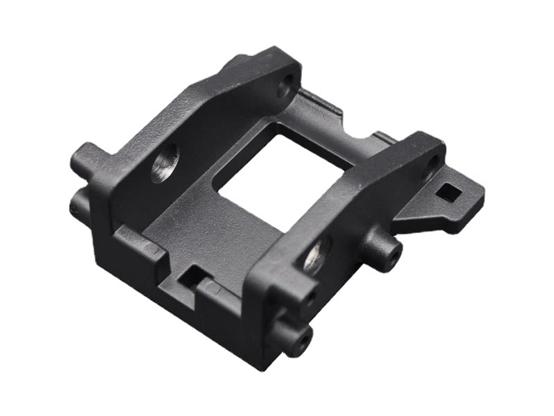
| CNC-machined metal | Metallic mass, machined appearance and compatible finish screening | Stock microstructure differs from casting; inaccessible areas and tool marks | As-cast skin, porosity, alloy condition and production finishing window |
| Prototype metal casting | Metal substrate and selected casting/finish interactions | Prototype process may create different roughness and defects | Production tool, process parameters, cavity condition and capability |
Choose the route that answers the current appearance question with the fewest unsupported substitutions. The 3D printing route may be efficient for one evolving model, while repeated molded samples may justify urethane casting. A metal appearance test may require a real metal substrate when coating chemistry or reflected highlights depend on it.
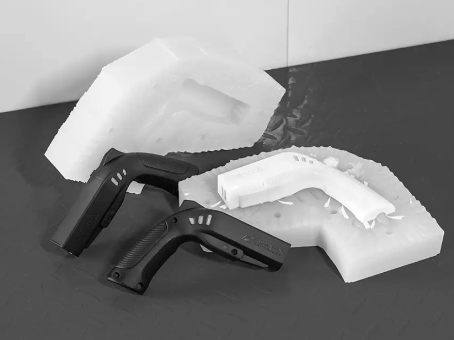
In urethane casting, silicone records the approved master together with wanted texture and unwanted defects. Support scars, sanding waves, filled pinholes, sharp repair boundaries and inconsistent primer can transfer into the mold. Approve the final master after its complete preparation, not the raw printed or machined source.
Separate geometry correction from cosmetic preparation. Repeated sanding can soften shutoffs, small radii, logos and assembly edges. Filling can change local contour. Inspect critical interfaces after surface work and before molding, and record which faces may be reworked without invalidating dimension evidence.
A high-gloss master demands close control because reflected highlights reveal waviness and dust. A textured master may conceal some fine process marks but can make later repair visible. The urethane finish-sample approval plan should identify the controlled master revision and the zone represented by each sample.
A molded surface is not only texture. Silicone mold splits, planned cuts, gates and vents leave witnesses that require acceptance or removal. Place them away from primary viewing zones, datums and fine edges where geometry permits. When no hidden route exists, show the expected witness on the appearance drawing and approve a representative part.
Trimming can pull material, round an edge or expose a color difference. Repair may alter gloss or texture near the witness. Define whether a seam may remain, be flush-trimmed, be filled and painted, or be rejected. The right answer depends on the review purpose and whether the production process will leave a different witness.
Air traps and incomplete fill can create pinholes or local surface loss. Review casting orientation, gates and vents before the mold is made, then inspect a raw first casting before applying primer or paint. Coating should not be used to hide an unresolved molding defect whose cause may continue through the lot.
Pigment in the cast polyurethane can provide through-color and avoid a separate coating layer. Its visible result depends on resin, pigment, mix, part thickness, mold surface and cure state. It may be suitable for a molded-color concept, but it should not be presented as evidence for the production resin without a defined comparison.
Paint can establish a controlled visual system across unlike prototype substrates. It also adds primer, film build, masking, cure, edge coverage and adhesion variables. The painting route should be qualified on the exact prototype resin or metal condition, including release-agent removal and any filler or primer used in repair.
Where production color will be molded rather than painted, approve the prototype as an appearance target and label the process difference. A sprayed clear coat can create depth and gloss that a molded polymer may not reproduce. Conversely, molded texture and flow can change perceived color even when a flat plaque is close.
Surface preparation establishes adhesion and reflected appearance. Cleaning removes oils, dust and release residue; abrasion or blasting changes roughness and gives a coating a mechanical key; filler and primer level local defects. Each step can also erase edges, texture and fine markings if it is too aggressive.
Use process coupons and representative features to establish the sequence. The surface-preparation review should connect contamination, roughness, substrate defects and coating failure modes. A preparation route developed on machined stock may need revision for a porous casting or cast polyurethane.
Do not accept a cosmetic repair without checking what caused the defect. Dust nibs and local scratches may be repairable; recurring bubbles, moisture reaction, coating fisheyes or substrate print-through call for process correction. Record repair location and method when the approved standard limits visible rework.
Blasting can unify directional tool marks, create a matte appearance or prepare a metal surface for coating. Media, pressure, distance, angle and substrate hardness affect texture and edge retention. The sand-blasting process should be trialed on representative geometry rather than specified as a universal way to conceal defects.
Polishing removes material to reduce roughness and control reflection. It can expose porosity in cast metal, round lettering, change flatness or produce different brightness across hard and soft microstructural regions. Mark surfaces that may be polished and protect datums, sealing faces and sharp appearance boundaries.
A matte prototype and a polished production part may both be called high quality while communicating different design intent. Finish choice should follow the intended viewing and use condition, not a simple ranking from rough to glossy.
Anodizing, conversion treatment, plating, powder coating and liquid paint respond to alloy chemistry, surface preparation and substrate condition. A machined wrought aluminum prototype cannot by itself predict the color or uniformity of a high-silicon die casting. If anodized appearance matters, state alloy and process route and validate production-intent samples.
The drawing details for cosmetic aluminum anodizing should include appearance zones, alloy/temper or casting grade, treatment type, color, sealing, masking, contact locations and acceptance method as applicable. Prototype approval establishes intent only within its documented substrate and process.
Powder coating requires a temperature-compatible substrate and attention to outgassing, film build and masking. Cast metal porosity or trapped contamination can produce bubbles during cure. A low-temperature polymer model generally cannot be assumed to follow the same powder route as a metal production part; a liquid coating may simulate appearance while leaving durability open.
Final aesthetics include gaps, flushness, seam alignment, fastener seating and transitions between materials. Inspect the assembled prototype after all coatings, graphics, bonding and hardware installation. A coating accepted on a loose component can chip at assembly or change a designed gap.
Mask threads, grounding points, connector seats, bond zones and precision fits where the coating is not allowed. State whether dimensions apply before or after finish. When film build matters, inspect the functional relationship in its assembled state rather than assuming nominal coating thickness is uniform on every edge and recess.
Handling and packaging are part of surface control. Glossy panels, soft coatings, painted corners and textured urethane can be scratched, polished or pressure-marked after inspection. Define protective contact, separators, bags and cleaning restrictions for the delivered state.
An attractive master sample communicates the target but may not define acceptable variation. Where the lot matters, establish an approved target plus limit examples for relevant defects such as seam evidence, color shift, gloss variation, orange peel, texture interruption, pinholes, scratches and repaired areas. Identify which zones each limit governs.
Use first-article approval before completing repeated casting or finishing. The submitted evidence should name CAD/master revision, mold, resin or alloy, preparation, finish stack, color batch, cure/conditioning, assembly and inspection condition. Approval of one face should not silently release all surfaces or later mold/finish batches.
If more than one silicone mold, paint batch or operator route is used, compare outputs against the same standard. Mold wear can soften texture or increase flash; finish batches can shift appearance. Define resubmission triggers before production of the prototype lot.
Visual inspection should reproduce the approved viewing condition and avoid searching for defects outside the specified use condition unless that examination is explicitly required. Clean the part with an approved method and allow coatings or polyurethane to reach the defined condition before judgment.
Instrument readings can supplement visual comparison. Color, gloss, coating thickness and roughness methods need appropriate equipment, geometry and sampling locations. Texture replicas and curved glossy surfaces can defeat a simplistic single-number requirement. Correlate measurements with accepted visual samples before using them as disposition limits.
Record defect type and location, not only pass or fail. A map of recurring sink, bubbles, witness repair or edge chipping helps distinguish master, mold, casting, preparation, coating and handling causes. That diagnosis is more useful for production transfer than a heavily repaired prototype with no process history.
A prototype coating can support color, texture and feel approval without proving adhesion, abrasion, corrosion, chemical exposure, weathering or thermal cycling for the final product. State which tests are informational and which are release requirements. Use the actual production substrate and coating process when service performance controls the decision.
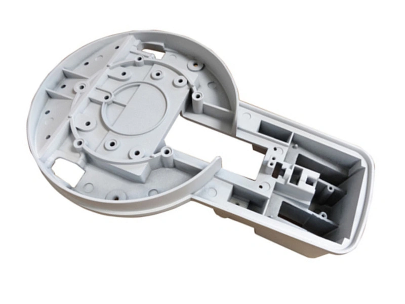
Likewise, a smooth urethane surface does not prove injection-mold flow, weld lines, sink, fiber read-through or ejection witness. A machined metal prototype does not prove die-cast porosity, flow marks, cavity wear or shot-to-shot variation. These are process-created conditions and must be evaluated on production-tool samples.
The prototype is most valuable when it closes product-intent questions early and preserves the remaining uncertainty. It should sharpen the production qualification plan, not make that plan disappear.
Release a surface-control package with controlled CAD/drawing, cosmetic-zone map, approved target and limit samples, texture source, color/gloss method, permitted witnesses, defect limits, masked functional areas, assembly condition, viewing method and prototype process history. Photograph standards with identifiers, but retain physical references where appearance cannot be captured reliably.
The production supplier then converts intent into process-specific controls: cavity polish or texture, gate/overflow/ejection placement, venting, substrate preparation, coating fixture and masking, inspection sampling and repair policy. The cosmetic surface standard should be reviewed against the chosen production process rather than copied without disposition.
Compare first production samples with the approved intent reference, but also inspect process-specific defects that the prototype could not contain. Record agreed differences. When the production material or texture changes reflected appearance, product engineering must decide whether to revise the standard, adjust the process or change the design.
Surface cost comes from master preparation, manual repair, texture creation, masking, coating layers, cure, inspection, approval samples, rejection risk, repeated molds or batches, packaging and documentation. The highest-cost requirement is often uniformity across difficult geometry or repeated parts, not the named coating itself.
Ask suppliers to separate base fabrication, cosmetic preparation, finish stack, samples, inspection and rework assumptions. Identify which defects are accepted as process witnesses. A realistic specification can reduce cost by concentrating control on visible zones and preserving functional areas in the state they need.
Changes after master or finish approval can invalidate mold, samples, masks, fixtures and work in process. Define approval authority and change terms. Early appearance decisions save money only when the approved source remains controlled.
Send controlled CAD/drawing, revision, prototype purpose, quantity and variants, target production material/process, cosmetic-zone map, texture and color references, gloss intent, permitted parting/gate/vent evidence, defect limits, masked functional areas, assembly state, environment, tests, reports, packaging and destination.
Ask the supplier to return the base process, master/substrate preparation, mold witness plan, resin/alloy and finish stack, repair policy, sample sequence, inspection conditions, measurement methods, batch controls, resubmission triggers, production-transfer limitations and dated approval points. Require deviations to be visible before fabrication.
A production-quality prototype surface is credible when the appearance target, process route and acceptance evidence agree. It can become a strong design reference and reduce ambiguity at tooling release. Production equivalence still depends on validating the final material, tool and finishing process under their own conditions.
What processes can achieve production-quality surfaces on early prototypes?
How do material choices affect achievable surface finishes during prototyping?
What post-processing steps help prototypes match final production aesthetics?
How closely can urethane or metal prototypes simulate injection-molded or die-cast surfaces?
How does Neway ensure prototype surfaces transition smoothly into mass-production tooling?