Powder Coating Thickness for Die Cast Parts: Fit, Masking and Inspection Decisions
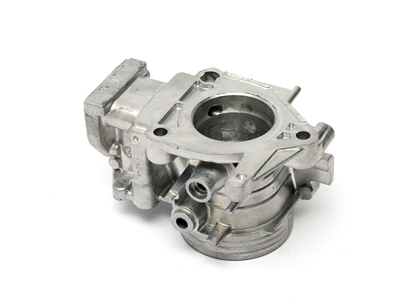
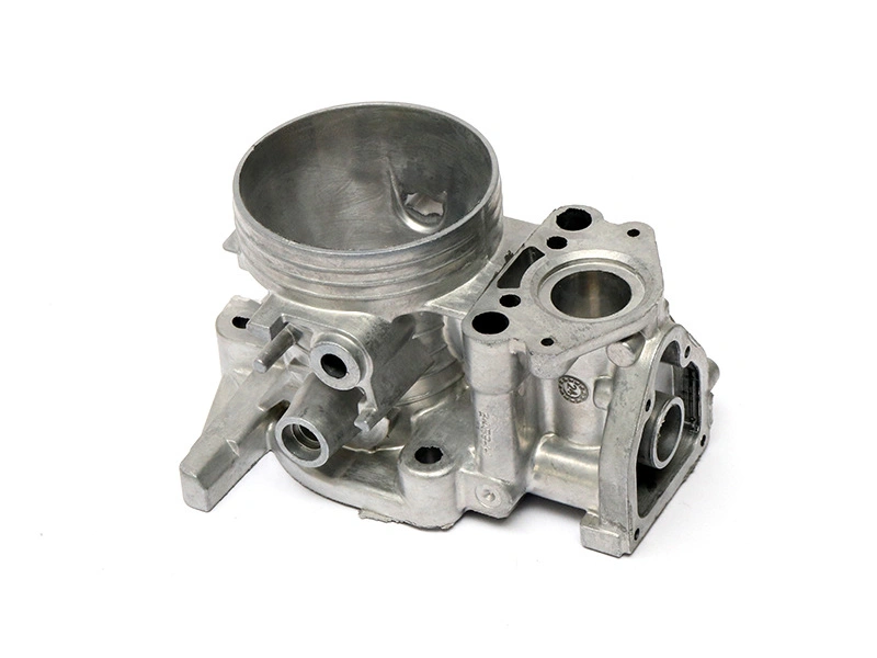
Powder coating thickness for die cast parts must be treated as part of the dimensional design, not only as a finish note. Film deposited on one surface adds to that surface; film deposited on both sides of a hole, slot or gap reduces the available opening by the combined buildup. A nominal coating value therefore affects press fits, bearing seats, sliding clearances, threaded engagement, gasket compression and assembly access in different ways.
Many industrial powder systems are discussed in approximate dry-film ranges around 60 to 120 micrometers, but that is a screening range, not a Neway capability statement or a substitute for the approved powder data sheet. Chemistry, substrate, pretreatment, geometry, appearance, cure and service exposure can require a different window. A drawing should state the controlled requirement and where it applies.
The practical decision is not “How thick is powder coating?” as one number. Buyers need a nominal target, allowable minimum and maximum, a surface-zone map, repeatable measurement locations, protected interfaces and a reaction plan for local readings outside the map.
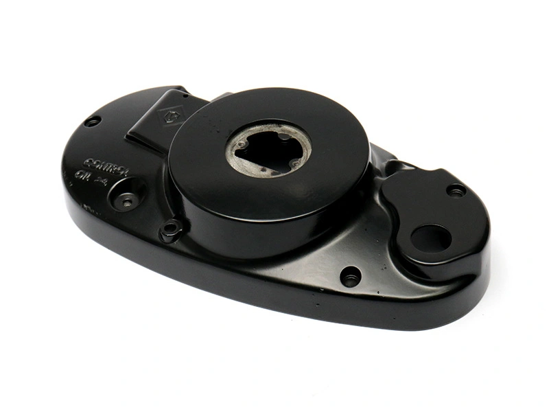
Why One Powder Coating Thickness Number Is Not Enough
Electrostatically applied powder does not create perfectly uniform buildup on a three-dimensional casting. Exposed flats may receive powder readily, projecting edges can accumulate more during repeated passes, and deep recesses may receive less because the electric field and spray path limit deposition. Racking orientation, gun distance, voltage, grounding, powder flow and operator or robot path also affect local distribution.
A specification that states only “80 micrometers” leaves several questions unanswered. Is 80 the target, minimum, maximum or average? Does it apply to every accessible surface, only cosmetic faces or only a test coupon? Are edges and recesses exempt? Is the acceptance based on individual readings or an average of a defined group? Can a thick local area be accepted if it does not affect function?
Requirement Element | Question to Resolve | Useful Output |
|---|---|---|
Nominal target | What process center supports the approved system? | Target range tied to powder data and trial |
Minimum | Where is coverage or protection essential? | Minimum by functional or exposure zone |
Maximum | Where can excess buildup affect fit or appearance? | Maximum at interfaces and cosmetic zones |
Measurement map | Which locations can be measured repeatably? | Numbered points with gauge and sampling method |
Exceptions | How are edges, recesses and inaccessible areas judged? | Visual, functional or witness-coupon rule |
Powder family matters as well. Buyers comparing exterior and interior systems can review polyester powder coatings for outdoor die cast applications and epoxy powder coatings for indoor parts. Those choices influence the approved film window, but the part drawing still owns dimensions and interfaces.
How Single-Side and Double-Side Buildup Change Dimensions
A coated outside surface increases outward approximately by the local film build. A coated bore loses approximately two times the local film build in diameter because powder occupies both sides. A coated slot narrows by the sum of the films on opposing walls. These are first-order dimensional estimates; local edge buildup, texture and measurement uncertainty still need consideration.
For example, if a design uses a 0.10 mm nominal film on both walls of a clearance slot, the nominal opening can decrease by about 0.20 mm. If the drawing permits a film range rather than a single value, the worst-case clearance calculation should use the relevant maximum on both sides. The same logic applies to a bore, but a press fit usually should not be created by relying on an uncontrolled organic coating layer.
Feature | First-Order Coating Effect | Preferred Control |
|---|---|---|
External boss | Outside dimension increases by local single-side build | Allow buildup or mask the fit diameter |
Internal bore | Diameter decreases by combined opposing films | Mask precision seats; gauge after coating |
Slot or gap | Available width decreases from both walls | Calculate worst-case assembly clearance |
Flat interface | Stack height changes by one or two coated faces | Define coated mating condition in stack analysis |
Thread | Flanks and roots lose usable clearance | Mask, plug or use an approved post-coat strategy |
The casting and machining drawings should use the same surface ownership. A dimension measured before finishing cannot automatically release the delivered part. When post machining of cast parts creates bores, threads or sealing lands, the process plan should identify which dimensions are checked again after masks are removed.
Which Features Should Be Coated, Masked or Thickness-Controlled?
Masking is usually justified when coating would interfere with function, electrical continuity, sealing, precision fit or thread engagement. Not every hidden surface needs masking, and excessive masking raises labor, transition-edge and residue risk. The decision should come from the assembly function and exposure map.
Feature | Typical Direction | Decision Evidence |
|---|---|---|
Bearing or bushing seat | Mask | Fit tolerance, retention method and surface requirement |
Clearance hole | Coat or plug depending on available clearance | Fastener size, maximum buildup and assembly trial |
Internal thread | Usually plug for controlled engagement | Thread class, torque and grounding requirement |
Gasket land | Project-specific | Seal material, compression, roughness and corrosion exposure |
Grounding pad | Mask | Electrical resistance and contact area |
Cosmetic exterior | Coat with appearance and thickness zone | Approved finish master and viewing condition |
Mask boundaries need dimensions or stable geometric references. “Keep powder away from the hole” is not inspectable. A transition band can recognize that a perfectly sharp coating edge is unrealistic while still protecting the functional interface. Plug insertion depth, flange overlap and allowable feather edge should be part of first-article approval.
Why Recesses, Edges and Deep Holes Do Not Build the Same Film
Powder particles follow the electrostatic field and carrier-air path. At a deep recess, field lines tend to concentrate near the opening while the enclosed area becomes harder to charge. This behavior is often described as a Faraday-cage effect. More voltage is not always the answer because excessive charging can worsen back-ionization or make deposition at the recess less stable.
Exposed edges create the opposite control problem. A gun pass that tries to reach a recess may repeatedly cross the surrounding rim, increasing local buildup. Sharp edges can still have reduced effective protective coverage after flow because liquid coating pulls away from a small radius. “Heavy near the edge” and “good edge protection” are therefore not interchangeable conclusions.
The supplier may adjust grounding, gun angle, powder flow, voltage strategy, part orientation and application sequence. Geometry changes such as a larger internal radius can also improve access. Approval must still use the actual casting, because a flat witness panel cannot reproduce a recessed pocket or narrow rib spacing.
How to Build Coating Allowance Into the Design
Start with the functional minimum and maximum of the delivered assembly, then work backward. Identify whether zero, one or both mating surfaces are coated. Add the maximum permitted coating build to the worst-case substrate dimension in the direction that reduces clearance. Include casting and machining variation, positional variation, seal compression and measurement uncertainty where relevant.
Do not solve every conflict by increasing clearance. A larger gap can create movement, leakage, noise or poor alignment. Precision interfaces are often better kept bare and protected by masking, conversion treatment or a separately approved corrosion route. The broad post-process service decision should connect dimensional needs with finishing rather than selecting the finish after the drawing is frozen.
Allowance Step | Input | Output |
|---|---|---|
Define delivered function | Required fit, movement, seal or contact | Minimum and maximum assembly condition |
Identify coated faces | Surface-zone and mask map | Single-side or double-side buildup path |
Apply worst-case build | Approved local maximum thickness | Coated dimensional limit |
Add substrate variation | As-cast and machined tolerance | Complete dimensional chain |
Choose control | Risk and production practicality | Allowance, masking or post-coat operation |
How Powder Coating Thickness Should Be Measured on Aluminum Castings
Nonferrous aluminum substrates are commonly measured with an eddy-current dry-film-thickness instrument. Standards such as ASTM D7091 or ISO 2360 may be referenced when applicable, but the drawing or quality agreement must state the governing method and acceptance rule. A standards name alone does not define the correct probe, calibration, number of readings or local geometry allowance.
The gauge should be verified on a substrate and curvature representative of the part, using traceable shims or standards within the expected range. Rough cast texture can increase reading scatter because the probe responds to local peaks and valleys. Small radii, thin edges, nearby corners and narrow bosses may fall outside the instrument manufacturer's accuracy limits. Measurements should avoid invalid zones unless a qualified method has been established for them.
Measurement locations must be reproducible. Numbered points on a drawing or photograph are stronger than “check several areas.” Record whether one reported value is a single reading, the average of repeated readings at one spot or an average across a zone. The quality plan should not average a locally thin critical area together with an unrelated thick flat and declare the part acceptable.
What a First-Article Thickness Map Should Prove
The first article should show distribution across cosmetic flats, protected exterior areas, edges, recess openings, representative interior zones and fit-critical boundaries. It should also verify bores, slots and threads in the final delivered condition. For aluminum die cast parts, the approved map should be tied to part revision, rack orientation, powder identity, application settings and cure record.
Production sampling can then focus on stable, measurable points that detect process drift. A witness coupon may support cure or color checks, but it cannot replace component measurements where geometry drives the risk. Changes to powder, rack, gun program, ground contact, geometry, supplier or specified thickness should trigger a documented review.
Map Zone | Release Question | Production Reaction |
|---|---|---|
Large cosmetic flat | Is finish and film build within the approved range? | Hold lot if repeated readings drift |
Recess opening | Does surrounding buildup hide a thin protected zone? | Review gun path and grounding |
Masked fit | Is the transition controlled and the gauge accepted? | Correct masking before recoat |
Edge or radius | Is the location measurable by the approved method? | Use visual or alternate qualified evidence |
Interior surface | Is coverage required, measurable or visual-only? | Apply the zone-specific acceptance rule |
How to Separate Film Thickness, Cure and Appearance Evidence
Dry-film thickness is only one control characteristic. A reading inside the approved range does not prove that the powder reached the required part-metal cure, bonded to the prepared substrate or matched the approved color and texture. Likewise, a glossy, smooth surface can be under the minimum protective build or can hide an excessive local stack at a fit interface. The inspection plan should keep these evidence types separate and then release the finished component only when all applicable checks pass.
Cure evidence normally comes from a qualified time-at-part-metal-temperature route or another method accepted for the coating system. Appearance evidence comes from a color, gloss and texture master under defined viewing conditions. Adhesion evidence uses the specified test method and specimen condition. Thickness evidence comes from the mapped gauge readings. Combining them into one statement such as “coating acceptable” makes later fault isolation difficult.
Evidence Type | What It Can Support | What It Does Not Prove Alone |
|---|---|---|
DFT readings | Local film build at valid probe locations | Cure, adhesion or field durability |
Oven or part-temperature record | Thermal route for the approved powder | Uniform thickness or substrate cleanliness |
Adhesion test | Coating-system bond under the stated method | Fit at bores or threads |
Finish master | Color, gloss and texture comparison | Minimum protection in hidden recesses |
Functional gauge | Delivered assembly interface | Coating build on unrelated surfaces |
This separation also improves change control. A new powder batch may trigger color and application checks; a revised rack can trigger distribution mapping; a heavier casting section can trigger cure verification; and a revised machined bore can trigger functional gauging. Repeating every test for every change is inefficient, but repeating none of them breaks the evidence chain.
Inspection reports should preserve raw values and their map references rather than showing only a pass statement. Raw readings allow buyers to see whether the process is centered, drifting toward a limit or varying by rack position. Trend review is especially useful when a feature has little dimensional margin: corrective adjustment can occur before the next lot crosses the acceptance boundary. Records should also identify approved exceptions, because an edge evaluated visually must not appear as a missing inspection entry.
Hypothetical Dimensional Chain for a Coated Die Cast Cover
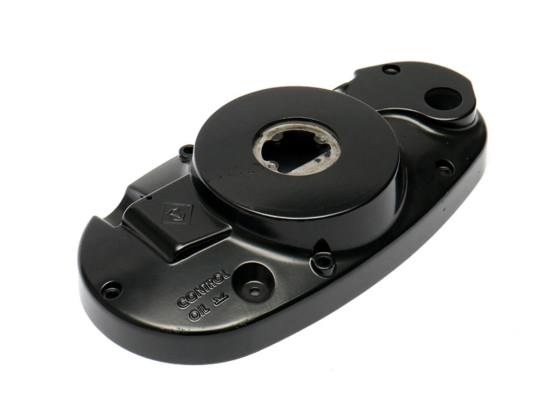
Consider a hypothetical die cast cover with a machined bushing seat, four tapped holes, a clearance slot and a coated outer locating shoulder. The bushing seat is masked because retention depends on a controlled metal diameter. The tapped holes use plugs because coating on the flanks would change engagement and torque. The clearance slot remains coated, so its machined width includes the maximum film allowed on both walls.
The first article records substrate dimensions before coating and functional dimensions after plug removal. Thickness points are placed on a representative exterior flat, near the slot without violating probe edge limits and at a recessed protected zone. The outer shoulder is evaluated in the coated condition because it contacts a nonprecision guard rather than a bearing.
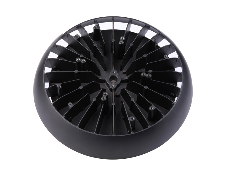
This scenario demonstrates the calculation and release sequence. It is not evidence that the pictured parts use a bushing, meet a stated tolerance or were measured by Neway. The actual map must come from the buyer's drawing, coating system and assembly stack.
What to Include in a Powder Coating Thickness RFQ
An RFQ should include the 3D model, controlled 2D drawing, casting alloy and route, incoming surface condition, powder specification, nominal/minimum/maximum thickness by zone, cosmetic class, mask drawing, fit-critical dimensions, measurement standard, gauge expectations, sampling plan and required first-article records. State whether dimensions apply before or after coating.
Buyers comparing powder with another finish can review when painting or powder coating may be chosen instead of anodizing. The choice still needs a fresh dimensional review because anodic conversion and organic film buildup do not affect interfaces in the same way.
RFQ Input | Why It Is Needed | Required Supplier Response |
|---|---|---|
Surface-zone drawing | Separates coated, masked and transition areas | Mask feasibility and boundary proposal |
Thickness map | Defines local limits instead of one vague value | Measurable points and method limitations |
Fit stack | Shows where one- or two-sided buildup matters | Allowance or masking recommendation |
Sampling plan | Controls first article and repeat lots | Inspection frequency and records |
Nonconformance rule | Prevents unapproved averaging or recoating | Containment and disposition workflow |
A robust thickness requirement connects geometry, function and measurement. It allows the coating process to vary within a proven window while protecting the interfaces that determine whether the finished die cast part assembles and performs as intended.
FAQ
How Does Powder Coating Change a Bore, Slot or Press-Fit Dimension?
Which Threads Should Be Masked Instead of Coated on Die Cast Parts?
Where Should Powder Coating Thickness Be Measured on Complex Castings?
Why Is Powder Coating Often Thin in Recesses and Heavy Near Exposed Edges?
How Should Buyers React When Local Powder Thickness Is Outside the Approved Map?