Zamak 3 for Zinc Die Casting: Strength, Dimensional Stability and Finish Decisions
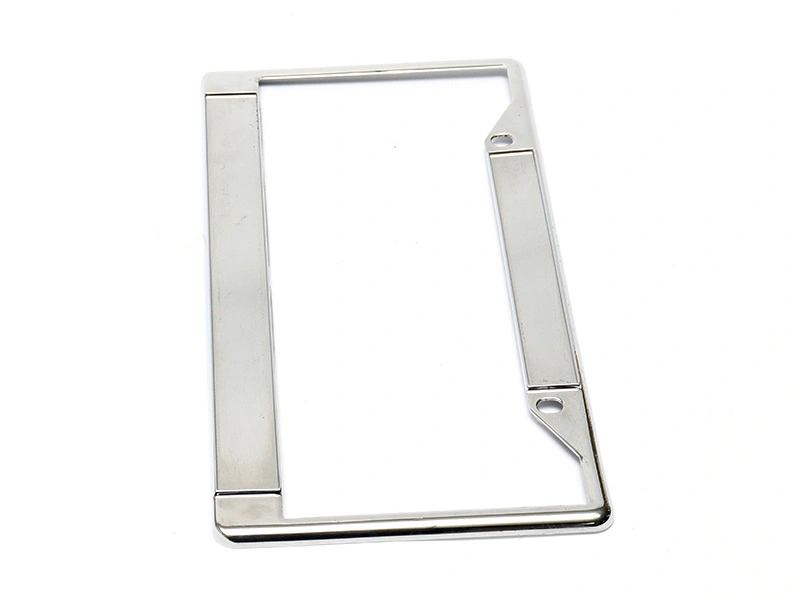
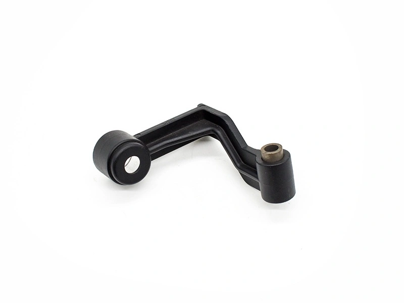
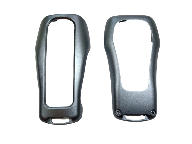
Zamak 3 zinc die casting is a practical route for lock housings, handles, connector shells, knobs, brackets and decorative hardware that need fine cast detail, stable production dimensions and a finish such as copper-nickel-chrome plating, painting or powder coating. The alloy is identified as ASTM AG40A in common North American specifications and is widely associated with hot-chamber die casting.
The useful purchasing question is not whether Zamak 3 is popular. It is whether its low-copper chemistry, room-temperature mechanical properties, creep behavior, casting geometry and surface response match the actual part. A visible connector cover with two lightly loaded screws is a different decision from a latch carrying repeated contact load or a boss clamped near a heat source.
Approval should connect the alloy certificate to the drawing, tool trial, machined features, finish master and dimensional records. A property table copied from a datasheet can screen the alloy, but only production-intent samples prove whether the finished part meets assembly, cosmetic and service requirements.
When Zamak 3 Is a Good Material Choice
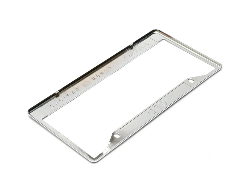
Zamak 3 is strongest as a purchasing choice when geometry and surface quality matter as much as short-term strength. Zinc's casting behavior supports thin sections, lettering, small ribs and compact bosses, while the alloy can provide a clean base for decorative finishing when gates, vents, parting lines and polishing allowances are designed around the visible face.
Lock bodies, control knobs, electrical connector shells and furniture hardware are common candidate geometries because they combine detail, moderate structural demand and repeat volume. This does not mean every part in those categories belongs in Zamak 3. A connector mounted next to a sustained heat source needs creep review; a latch with sliding contact may justify Zamak 5; a large lightweight enclosure may favor an aluminum route.
Volume also affects the choice. Hot-chamber tooling and automation can make repeat production efficient, but the buyer must have enough design stability to approve tooling. For an evolving low-volume concept, machining a prototype can answer shape and assembly questions before a casting tool is justified.
Buyer Requirement | Why Zamak 3 Fits | Planning Condition | When to Compare Another Route |
|---|---|---|---|
Fine detail and compact features | Hot-chamber casting can reproduce small ribs, lettering and bosses | Gate, vent, draft and ejector layout must support the detail | Use machining for unstable designs or very low quantity |
Decorative plated face | Zamak 3 can provide a polishable zinc base | Approve the finish on actual cast samples | Change finish or alloy if porosity and service exposure cannot be controlled |
Dimensionally repeatable hardware | Tooling and gauges support consistent interfaces | Separate as-cast, machined and coated dimensions | Use a machined route for extremely tight low-volume features |
Moderate mechanical load | Typical room-temperature properties suit many housings and handles | Validate bosses, threads and real load direction | Review Zamak 5 or another metal for wear, heat or sustained high load |
Zamak 3 Composition and Property Values Buyers Should Verify
The ASTM AG40A chemistry direction is approximately 3.7-4.3% aluminum, 0.02-0.06% magnesium and no more than 0.10% copper, with zinc as the balance and impurity limits controlled by the invoked specification. Buyers should use the current purchased standard, not a web summary, as the contractual source. The Zamak 3 material page is useful for early comparison, while the supplier's lot certificate confirms the delivered melt.
Published room-temperature die cast values often show tensile strength around 280 MPa, yield strength around 220 MPa, elongation near 10%, Brinell hardness around 80 and density near 6.6 g/cm3. Values vary with the standard, specimen, casting process, section and test condition. They should not be copied onto a component drawing as guaranteed minima unless the supplier and buyer agree on a test method and acceptance basis.
Property or Chemistry | Typical Direction | Buyer Relevance | Verification Record |
|---|---|---|---|
Aluminum | About 3.7-4.3% under common AG40A references | Contributes to strength and casting behavior | Actual chemistry against the invoked standard |
Copper | Very low compared with Zamak 5 | Separates the grade and influences property trade-offs | Lot chemistry and approved-equivalent review |
Tensile and yield strength | Approximately 280 MPa and 220 MPa screening values | Supports early section and load review | Applicable standard or agreed coupon test |
Elongation and hardness | Roughly 10% elongation and about 80 HB as typical directions | Helps compare ductility, denting and wear needs | Supplier data tied to test condition |
Part performance | Controlled by local geometry and casting integrity | A thin boss does not equal a standard tensile specimen | Functional test on production-intent castings |
Zamak 3 vs Zamak 5: Dimensional Stability or Higher Strength?
Zamak 5 contains more copper than Zamak 3 and is commonly chosen when higher hardness, strength or wear resistance provides a measurable benefit. Zamak 3 generally retains the advantage for broad-purpose castability, ductility and dimensional stability. The choice should begin with the failure mode, not with the assumption that a higher-strength grade is automatically better.
For a plated connector shell, thin-wall filling, thread position and cosmetic consistency may favor staying with Zamak 3. For a latch with sliding contact or a compact lever base with higher local load, Zamak 5 can be evaluated. The published comparison in Zamak 3 versus Zamak 5 selection gives the broader alloy context, but the final decision belongs to the actual stress, temperature, surface and service test.
Decision Factor | Zamak 3 | Zamak 5 | Buyer Choice Signal |
|---|---|---|---|
Copper direction | Low copper AG40A chemistry | Higher copper AC41A chemistry | Confirm grade on certificate; do not approve by trade name only |
Strength and hardness | Suitable for many moderate-load parts | Higher typical values | Choose Zamak 5 only when load or wear data justify it |
Ductility and stability | Often preferred for general detailed castings | Trade-offs require review | Stay with Zamak 3 for validated cosmetic and dimensional designs |
Sustained load | Needs creep validation | Also needs creep validation | Neither grade should be released from tensile data alone |
Finish | Established base for plating and painting | Can also be finished | Approve the selected alloy with the actual finish route |
Which Part Features Need DFM Review With Zamak 3?
Thin walls, tall ribs, isolated bosses, abrupt section changes, deep cores, undercuts and visible faces need focused DFM. Zamak 3 can fill fine features, yet long flow paths and poorly vented last-fill regions can still produce cold shuts or trapped gas. A solid boss attached to a thin panel can create shrinkage and cosmetic read-through even when the rest of the part fills cleanly.
Early review should overlay gate direction, vent locations, parting line, slide travel, ejector support and trimming. Tool and die planning is particularly important where a cosmetic face conflicts with a gate vestige or where a no-draft feature requires a slide. Steel-safe inserts can preserve room for trial correction on critical shutoffs, hole positions or wall features.
Feature | Casting Concern | Design Action | Evidence at Trial |
|---|---|---|---|
Thin wall after a long flow path | Cold shut or incomplete fill | Shorten flow, balance transitions and preserve venting | Consecutive warm-die parts fill without cosmetic repair |
Rib intersection | Local thermal mass and gas trap | Thin the node and add fillets without a solid block | No sink, read-through or internal discontinuity at the junction |
Screw boss | Porosity, base cracking or creep | Core the boss and spread load through ribs | Thread, torque and sustained-load tests pass |
Deep internal wall | Core grip and ejection distortion | Add suitable draft and tool polish | No drag marks; inside dimensions remain stable |
Visible plated face | Parting line, gate or ejector evidence | Move marks to controlled non-cosmetic regions | Approved plated master from actual castings |
How Threads, Inserts and Machined Features Should Be Planned
The most economical route is not always to cast every feature. A coarse external thread in a favorable draw direction may be cast, while a small internal thread with a position requirement is often better cored and tapped. A bearing or locating bore may need reaming or CNC machining from assembly datums. Inserts can improve repeated service, but the surrounding zinc must still carry pullout and torque loads.
Define the feature route before the tool is frozen because core size, machining stock, fixture access and datum pads affect the cavity. The guidance on when Zamak casting needs CNC machining helps identify only the functional features that need secondary control. Machining every surface adds cost and can expose local porosity without improving the part.
Feature | Cast, Insert or Machine | Control Method | Acceptance Tool |
|---|---|---|---|
Coarse external thread | Cast when release and parting line permit | Protect working flanks and trim flash | Functional ring gauge |
Position-critical internal thread | Core pilot then tap | Locate machining fixture from assembly datums | Thread plug gauge and position check |
Frequently serviced fastener | Consider installed or cast-in insert | Control installation and surrounding boss | Torque-out and pullout test |
Locating bore | Machine if fit exceeds as-cast capability | Leave stock and protect datum relationship | Plug gauge or CMM |
Nonfunctional relief or rib | Keep as-cast | Use realistic draft and edge criteria | Visual and profile check |
How Plating and Painting Change Zamak 3 Acceptance
Finishing changes what counts as an acceptable casting. Polishing for copper-nickel-chrome plating can reveal pores, parting-line mismatch and gate-removal marks. A reflective finish also makes waves and boss read-through visible. Painting and powder coating can hide small color differences, but they cannot reliably repair cold shuts, deep pores or dimensional mismatch.
Mark cosmetic zones and viewing conditions on the specification. Define whether tiny pits, flow traces or polishing transitions are allowed by zone. Threads, electrical contact points and tight fits may need masking. The supplier should produce the approved cosmetic master with the same cast alloy and preparation route described in surface finishes for Zamak die castings.
Finish | Surface Prerequisite | Common Defect | Approval Evidence |
|---|---|---|---|
Copper-nickel-chrome plating | Controlled porosity, polish direction and gate cleanup | Pits, blisters or visible parting-line transition | Plated cosmetic master and adhesion/process record |
Painting | Clean, prepared surface with defined primer route | Fish-eyes, poor adhesion or color variation | Color sample and adhesion check |
Powder coating | Heat-compatible part and controlled coating thickness | Buildup at holes, outgassing or orange peel | Thickness record and post-coat assembly gauge |
Polished as-finished surface | Adequate stock at the gate and parting line | Waves, exposed pores or over-polished edges | Defined viewing standard and retained master |
What Limits Zamak 3 in Heat, Creep and High-Load Applications?
Zamak 3 can lose load-carrying efficiency through creep when stress, time and temperature act together. A screw boss may retain its shape during assembly yet gradually settle under clamp load, reducing preload. A thin bracket near a warm motor may deflect more over its service life than a room-temperature tensile value suggests.
Do not use one absolute temperature as a universal pass/fail boundary. Measure the actual metal temperature, define sustained and cyclic loads, calculate the local stress direction and test production-intent geometry for the required duration. Short-term proof tests are useful for gross weakness but cannot replace load-retention or dimensional checks after conditioning.
Environment | Primary Risk | Validation | Alternative Direction |
|---|---|---|---|
Ambient decorative housing | Low structural risk; cosmetic and thread control dominate | Assembly, finish and routine dimensional tests | Stay with Zamak 3 when evidence passes |
Warm clamped joint | Preload loss through creep | Clamp-retention test at measured service temperature | Spread load, isolate heat or compare another material |
Sliding contact | Wear and local edge loading | Cycle test with real lubrication and surface condition | Review Zamak 5 or a wear insert |
High-impact or safety-critical load | Geometry-dependent fracture and damage tolerance | Application-specific impact and overload testing | Consider aluminum, steel or a redesigned load path |
Hypothetical Engineering Scenario: Plated Connector Housing With Tapped Holes
Consider a hypothetical production-intent connector housing being evaluated in Zamak 3 to combine a thin-wall window, fine external detail and a plated front face. An initial risk review would identify three linked issues: the window could sit near a last-fill area, two bosses would need tapped holes located from a mounting datum and polishing could expose flow or parting-line marks.
A suitable tool plan could adjust gate and vent direction so the thin window fills while displaced air still has an escape path. The bosses could be cored with machining stock rather than casting final threads. A fixture would locate from the mounting face and control both tapped-hole positions. Trial castings should then pass thread-gauge and mating-connector checks before polishing and plating.
If a finish trial revealed a visible transition at a gate-removal region, the team would need to correct that area and retain an approved plated cosmetic master. The valid conclusion would not be “Zamak 3 always plates well.” Approval would depend on a documented evidence chain linking AG40A chemistry, stable warm-die filling, tapped-hole position, assembly fit and the actual decorative finish.
What to Include in a Zamak 3 RFQ
A useful RFQ lets the supplier identify where Zamak 3 properties and zinc die casting geometry affect the quote. Send a 3D model and controlled 2D drawing, then state the grade, equivalent policy, critical walls, visible zones, fastening route, finish stack, annual demand and acceptance evidence. The broader Zamak alloy selection guide can support an early grade discussion, but the RFQ should identify the proposed grade clearly.
RFQ Field | Zamak 3-Specific Entry | Supplier Response | Approval Record |
|---|---|---|---|
Grade and standard | ASTM AG40A / Zamak 3 with controlled equivalent policy | Source, chemistry record and any proposed equivalent | Approved material specification |
Critical casting feature | Minimum local wall, rib junction, boss or visible gate restriction | Gate, vent, draft and steel-safe proposal | DFM and tool drawing approval |
Threads and inserts | Fastener, engagement, load, service cycles and gauge | Cast, tap, self-tap or insert route | Thread-gauge and functional test report |
Finish system | Copper-nickel-chrome, paint or powder coat with cosmetic zones | Preparation, masking and defect-control plan | Approved finish master |
Quantity and release | Trial quantity, annual demand, batch size and cavity data | Tooling, sampling and control-plan proposal | FAI and production release package |
How Buyers Release Zamak 3 for Repeat Production
Repeat production should use the same linked evidence that approved the sample. The material certificate identifies ASTM AG40A and the melt or lot. The drawing revision defines the datums, machined features and cosmetic zones. Tool records identify cavity changes, core-pin replacement and flash growth. The finish master controls appearance, while thread gauges and dimensional trend data protect assembly.
Use measurement and testing resources that match the characteristic: CMM for datum relationships, plug or thread gauges for functional interfaces, visual masters for plated surfaces and application fixtures for clamp or assembly performance. A report should identify cavity and lot whenever those identities affect containment.
Release Control | Zamak 3-Specific Risk | Required Record | Reaction Trigger |
|---|---|---|---|
Material lot | Unapproved chemistry or grade substitution | AG40A chemistry certificate linked to shipment | Missing field, out-of-limit result or new source |
Tool condition | Flash, core-pin wear or cavity shift | Maintenance log and cavity-specific checks | Trend or visual master moves toward limit |
Fastening | Thread wear, boss cracking or preload loss | Gauge, torque and applicable load-retention results | Tool, insert, screw or service condition changes |
Finish | Pits, coating buildup or cosmetic drift | Approved sample and finish process record | New finisher, preparation change or defect trend |
Version control | Mixing obsolete geometry or inspection logic | Released CAD, drawing, control plan and gauge revision | Any engineering change affecting form, fit or finish |
The release decision is therefore specific: use Zamak 3 when the documented chemistry, feature-level DFM, fastening tests, actual finish and repeat-order controls all protect the part's function. When heat, wear or load cannot be demonstrated within that evidence, compare Zamak 5, isolate the load or select another material route before committing further tooling and production cost.
FAQ
How Does Zamak 3 Creep Affect Bosses and Clamped Joints Under Sustained Load?
What Draft, Rib and Boss Proportions Work Best for Thin-Wall Zamak 3 Parts?
How Should Threads and Inserts Be Designed in Zamak 3 Die Castings?
Which Inspection Methods Catch Dimensional Drift in Zamak 3 Production?
What Material Certificate Should Buyers Require for ASTM AG40A Zamak 3?