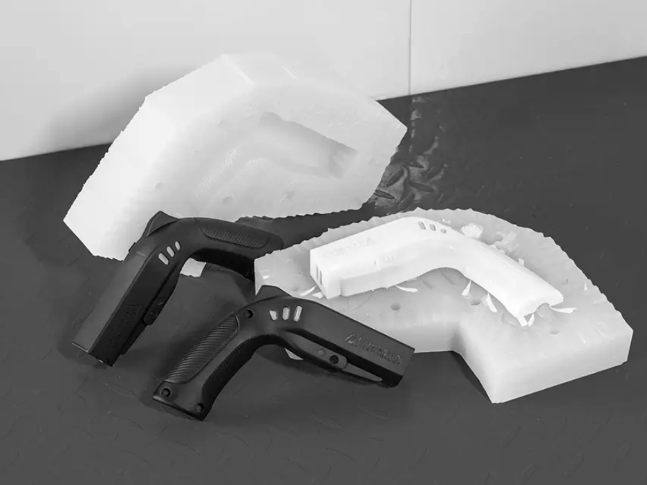
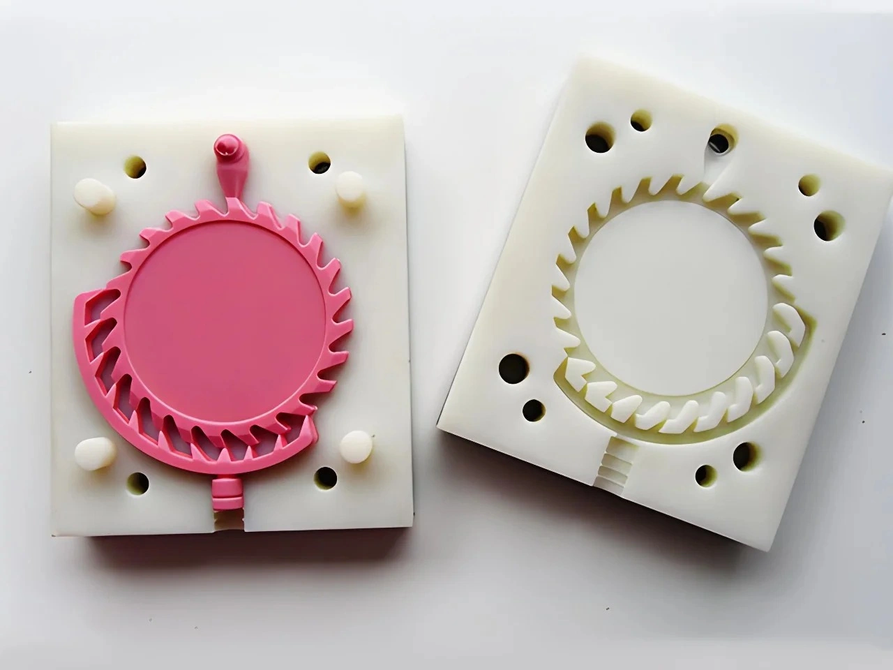
Urethane Casting Perfect for Complex Geometries and Multiple Materials
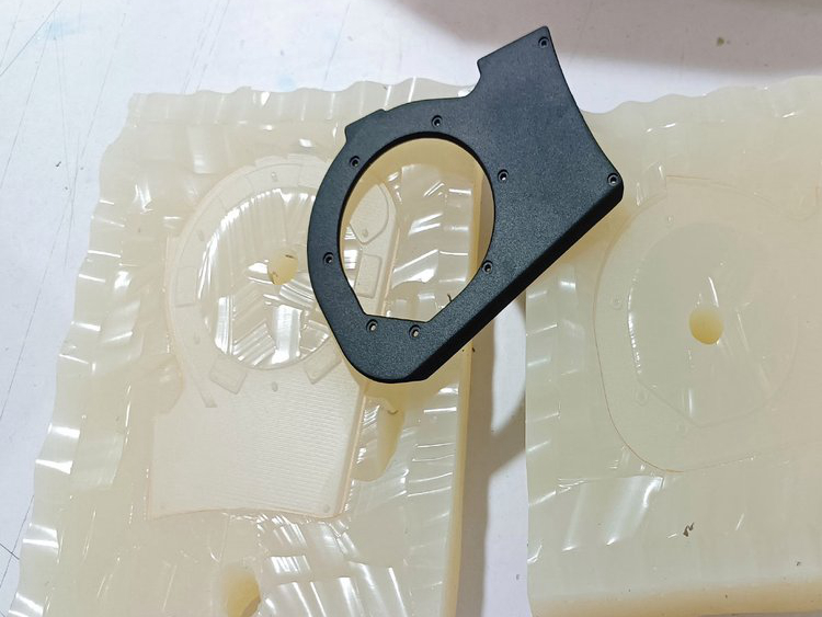
Urethane casting is a strong candidate for complex geometry and multi-material prototypes when every undercut has a demolding path, every enclosed region has a mold or assembly strategy, resin can fill and vent the part, and each material interface answers a defined test. Flexible silicone can release selected shapes without metal slides. It does not make trapped geometry, fragile details, heavy sections or incompatible materials disappear.
The buyer should begin with two separate questions. What geometric learning is needed: envelope, assembly, internal routing, clips, texture or integrated hardware? What material learning is needed: hardness contrast, grip location, seal compression, transparent window, color separation or interface concept? Combining these questions only makes sense when the prototype route and evidence boundaries are explicit.
Classify Complexity Before Selecting the Process
Complex is not a manufacturing specification. A smooth organic housing may be easy to mold but hard to finish. A small return can create severe mold strain. A deep open channel may fill readily yet trap air at its end. Classify each difficult feature by master production, mold construction, filling, venting, demolding, trimming, dimensional control and inspection.
Separate product complexity from production-process complexity. Silicone tooling can postpone the need for a metal slide while the design is being evaluated, but an eventual injection mold or die-casting tool still needs its own draft, parting, cores, ejection, gates and thermal strategy. Urethane evidence can validate the product question without validating the final tool.
Geometry and Material Risk Map
| Feature or concept | Urethane route | Main failure mode | Release evidence |
|---|---|---|---|
| Releasable undercut | Flexible mold peel or planned cut | Silicone tear, part distortion or witness | Demolding trial and mold-condition check |
| Internal passage | Multi-piece mold, removable core or assembled sections | Trapped core, seam, blockage or air | Core removal and passage inspection |
| Thin wall beside heavy boss | Controlled orientation, gates, vents and cure | Short fill, air, heat or dimensional bias | Raw first casting and conditioned measurement |
| Rigid-soft region | Sequential casting, bonding or mechanical retention | Mislocation, weak interface, flash or cure conflict | Section/interface review and bounded test |
| Insert or hardware | Cast-in, bonded or installed after casting | Movement, leakage, poor retention or blocked thread | Location, pull/torque or assembly check as specified |
This map should be feature-specific. A supplier cannot responsibly approve "complex geometry" from an overall image. Request a returned DFM view showing the split, planned cuts, loose pieces, cores, gates, vents, insert loading, trim access and surfaces that may carry process evidence.
Choose a Master Route That Preserves Difficult Features
The master may be printed, machined or assembled from both. Printing can create freeform geometry and internal detail with fewer tool-access constraints, but support removal and surface preparation can damage narrow slots, sharp edges and fine texture. Machining can establish accessible datums and mating faces, but deep recesses and organic forms may require several setups or separate pieces.
The 3D printing route should be reviewed with build orientation, support strategy, trapped material removal and final master finish. If an internal channel cannot be cleaned or inspected in the master, copying it into silicone will not resolve that uncertainty.
Inspect and approve the final prepared master. Filling, sanding and primer can close small holes, soften clips or shift assembly edges. Record which features are controlled by CAD and which by a physical master standard before mold making begins.
Design the Mold Around Release, Not Only Cavity Shape
Silicone flexibility is useful when the mold can deform within a safe path and recover. Undercut depth, return angle, feature stiffness, silicone thickness, extraction length and nearby cuts determine whether release is practical. A geometry may release once but damage the mold or part during repeated handling.
Plan the mold split and support shell together. Thin silicone around a protrusion can tear; a large unsupported block can distort; a planned cut can release a hook but leaves a seam and requires repeatable closure. The flexible-mold geometry review should state where bending is intentional and where it creates unacceptable strain.
Use loose pieces or removable cores when peeling would overload the mold or part. Identify how each piece is located, removed and reassembled. More mold pieces can solve release but add seams, flash, handling time and opportunities for positional variation.
Give Enclosed Features a Core or Assembly Strategy
A fully trapped cavity cannot be released merely because the tool is soft. It may require a sacrificial core, collapsible or removable element, a multi-piece mold, an opening in the design, or separate cast sections joined later. Each option changes surface, dimension, cleaning and test evidence.
For passages, define how the core is supported and how its position is verified. Buoyancy or resin flow can move a poorly located core. After removal, inspect continuity with a gauge, mating tube, visual method or another project-defined test. Do not infer a clear internal route from an acceptable exterior.
When separate sections are bonded, mark the joint as prototype construction. The seam may answer routing and assembly questions but not prove a one-piece production geometry or production joining method.
Design Gates and Vents for the Real Casting Orientation
Thin paths, high points, abrupt section changes, blind pockets and texture can trap air or stop fill. Choose an orientation that lets resin reach remote features while displaced air escapes. Gates need adequate delivery without placing a trim scar on a functional edge; vents need access for clean removal.
Flexible molds can change shape under handling or vacuum/pressure conditions used in the selected process. Support the mold and control closure so split mismatch does not move a thin wall or interface. Inspect the raw first casting for incomplete fill, bubbles, flash and distortion before adding paint or repair.
A first-part correction may involve gate/vent changes, mold cuts, resin handling or geometry. Keep those changes under revision control. A repaired finished sample can look acceptable while hiding a casting route that is not repeatable.
Manage Thin Features and Heavy Sections Separately
Thin walls and narrow ribs challenge flow, venting and demolding strength. Fragile projections may fill but break during trim or extraction. Heavy bosses and solid masses can create different cure heat, shrinkage and property state. A part containing both needs more than a generic wall recommendation.
Review transitions, local cores and split construction. A hollow or assembled feature may reduce mass while preserving the prototype question. If the design must remain solid, select resin and cure/conditioning with the supplier and verify the representative section rather than relying on a flat data-sheet sample.
Define when dimensions and functional tests occur. A freshly demolded thin wall and a conditioned assembly may not have the same state. Use a fixture or mating component where free-state flexibility makes coordinate measurement misleading.
Protect Fine Detail through Demolding and Finishing
Logos, microtexture, sharp ribs and delicate clips can be captured by the master yet lost through air, mold wear, tear, trimming or paint build. Identify the smallest details that affect the decision and approve them on the raw and finished first article.
Place parting, cuts, gates and vents away from fine detail where possible. If a witness crosses a visible or functional feature, show the planned repair and acceptance limit. Repeated hand finishing may blur detail differently across the lot.
Texture condition should be monitored as the silicone mold is used. Define replacement or resubmission triggers from actual surface and dimensional acceptance, not a universal mold-output claim.
Treat Inserts as Located Components, Not Fillers
Threaded inserts, magnets, bushings, contacts, windows and rigid cores need positive location and protection against resin leakage. Decide whether they are cast in, bonded, pressed or mechanically installed. Cast-in hardware can reduce assembly but complicates mold loading and may trap air or shift.
The insert and secondary-operation review should name locating datums, exposed surfaces, retention requirement and inspection. A metal insert can also change local stiffness and load transfer, so a passed assembly test applies to that documented construction.
Protect internal threads and electrical faces from resin and coating. Where retention matters, define a bounded pull, torque or functional test based on the prototype purpose. Do not invent a load target from the insert size alone.
Define What Multiple Materials Means
Multi-material may describe two polyurethane hardnesses, a rigid casting with an elastomeric region, a clear window in an opaque body, a cast-in metal insert, or separate parts bonded into an assembly. These routes use different molds, sequences and evidence. The RFQ should not use "dual material" without a zone map and interface purpose.
The dual-material simulation route may use sequential casting, separate casting plus bonding, or mechanical retention. Choose the route that represents the intended geometry and test while acknowledging that production overmolding uses different materials, pressure, temperature and interface preparation.
Select Each Resin by an Attribute and Test
Terms such as ABS-like, PC-like, PP-like or rubber-like are screening descriptions, not material specifications. State the attribute needed in each zone: hardness, initial stiffness, flexibility, clarity, color, short-term impact response, compression or tactile feel. Then define the test condition and production property that remains open.
The material simulation framework should lead from supplier data to coupon and representative part evidence. Production thermoplastic, elastomer or metal qualification still requires the specified grade and process, especially for heat, chemicals, creep, fatigue, aging or regulated use.
Record resin designation, color/additives, mix, cure/post-cure if specified, part age and conditioning. A rigid and soft region may reach test state at different times. Compare parts only under the agreed condition.
Choose an Interface Mechanism Deliberately
An interface can rely on chemical adhesion, mechanical interlock, adhesive bonding, hardware or a combination. Chemical bonding depends on the exact resin pair, surface condition and timing. Mechanical retention depends on geometry and fill around the feature. Neither should be assumed from visual continuity.
Design interlocks with flow, air escape and demolding in mind. Deep holes or sharp hooks may trap bubbles or tear soft material. An adhesive joint needs clean access, controlled bondline and cure. A mechanically retained insert needs location and load transfer without cutting the surrounding urethane.
Approve interface appearance separately from performance. A clean color boundary may still have weak adhesion; a visible seam may be acceptable for an ergonomic study. Section a sacrificial sample or use a project-specific peel, pull, compression or assembly test where interface integrity matters.
Plan the Sequential Casting Route
Sequential casting can use a first material or insert placed into a second mold state, followed by another resin. It is not necessarily a single closed-mold operation. The process may require separate masters, mold inserts, temporary blanks, masking, partial cure, demolding, repositioning or surface preparation.
Define which material is cast first, its cure state at the next operation, how it is located, and where flash or witness is allowed. Incompatible cure timing can deform the first element or weaken the interface. Color contamination and leakage at the boundary also need controls.
Use a traveler that identifies resin lots, mix time, cast sequence, cure, mold/insert revision and operator checkpoints. This record makes a functional result interpretable and supports correction if the boundary shifts or delaminates.
Inspect Geometry, Material and Interface at Separate Gates
First inspect the master and mold plan. Next inspect raw cast geometry, fill, air, parting, insert location and material boundary. Then condition the part and perform dimension, assembly, tactile or functional checks. Finishing should follow acceptance of the underlying construction unless the finish is itself part of the test.
Mark critical relationships and measurement state through the urethane dimension plan. For flexible zones, specify free, fixtured or assembled measurement. For multi-material parts, note which datum belongs to the rigid carrier and which feature is expected to deform.
Plan Sample Quantity around Evidence and Consumption
Complex and multi-material programs often consume parts during setup and verification. A raw casting may be sectioned to inspect a hidden channel or material boundary. Another may be used for a destructive interface test. Finish approval, dimensional inspection and assembly testing may need separate parts in defined conditions. Nominal casting quantity therefore may not equal accepted delivery quantity.
Build a sample allocation before quoting the lot. Identify first-off process review, sacrificial sections, conditioned test pieces, appearance standards, destructive tests, buyer-retained references and delivered assemblies. State whether a failed setup part belongs to the ordered quantity and what evidence releases continued casting.
Multiple silicone molds or mold states may be necessary when quantity, variants, large geometry or separate material zones exceed one practical tool route. Each additional mold adds master/mold cost, cavity comparison and its own wear history. Compare accepted outputs from all tools at the same inspection gate rather than assuming copies from separate molds are interchangeable.
Price the Complexity Drivers Explicitly
Tool price alone does not describe a complex urethane program. Cost also follows master segmentation, mold pieces, removable cores, insert loading, casting sequence, resin waste, manual demolding, trim, interface preparation, conditioning, inspection, rejected parts and mold replacement. A soft tool can carry substantial recurring labor even when it avoids metal slides.
Ask the quote to separate geometry-driven work from material-driven work. That visibility helps a buyer decide whether to simplify an undercut, join two sections, standardize a material zone or reserve a high-effort integrated prototype for only the tests that need it. It also makes design changes traceable to affected assets and operations.
Know When Another Route Closes the Question Better
Direct printing may be better for one changing internal route or a monolithic geometry that cannot be sensibly cored in silicone. CNC may be better for a precise stock-material interface, accessible sealing face or load test that polyurethane cannot represent. Injection samples may be required for weld lines, fiber orientation, molded adhesion or production material.
Separate assemblies may be more informative than an integrated dual-material casting when the production joining method is still open. A modular prototype lets teams change one region without remaking every mold and can expose interface loads directly.
Compare routes at the same accepted test state, quantity and revision exposure. The urethane prototype-fit review should include all tooling, preparation and qualification required for that state. Urethane casting earns its place when repeated copies, molded surfaces, selected material contrasts, embedded hardware or assembly trials justify the master and silicone-tool stages.
Carry Product Learning into Production without Copying the Process
Transfer controlled geometry, approved interfaces, assembly findings, appearance zones, material-attribute priorities, test results with conditions, prototype substitutions and open risks. Do not copy silicone parting, gates or flexible demolding assumptions into a production metal tool.
Injection molding, die casting and other long-term routes require their own DFM, material selection, tool design and samples. Draft, slides, lifters, ejection, cooling, flow and production joining must be developed for those processes. A successful urethane prototype narrows product uncertainty; it does not qualify the production process.
Complex Multi-Material RFQ Checklist
Send controlled CAD/drawing, revision, prototype question, quantity, target production process/materials, geometry risk zones, internal passages, appearance zones, undercuts, allowed splits/witnesses, inserts, material-zone map, interface purpose, target attributes, test state, finish, reports, packaging and destination.
Ask the supplier to return the master route, mold splits/cuts/cores, gates/vents, demolding sequence, wall/section risks, insert location, resin systems, cast sequence, interface mechanism, cure/conditioning, first-part gates, inspection, remake triggers and production limitations. Require every deviation before mold release.
Urethane casting is suitable for complex geometries and multiple materials when the complexity is converted into controlled manufacturing decisions. The credible result is a prototype that answers named questions with traceable construction, not a claim that flexible tooling removes every geometric or material constraint.
FAQs
Why is urethane casting ideal for complex geometries that traditional tooling cannot support?
What types of materials can be simulated using cast polyurethane?
How do multi-material or dual-durometer prototypes work in urethane casting?
When should engineers choose urethane casting instead of CNC or injection molding?
How does Neway ensure urethane prototypes transition smoothly into mass production processes?