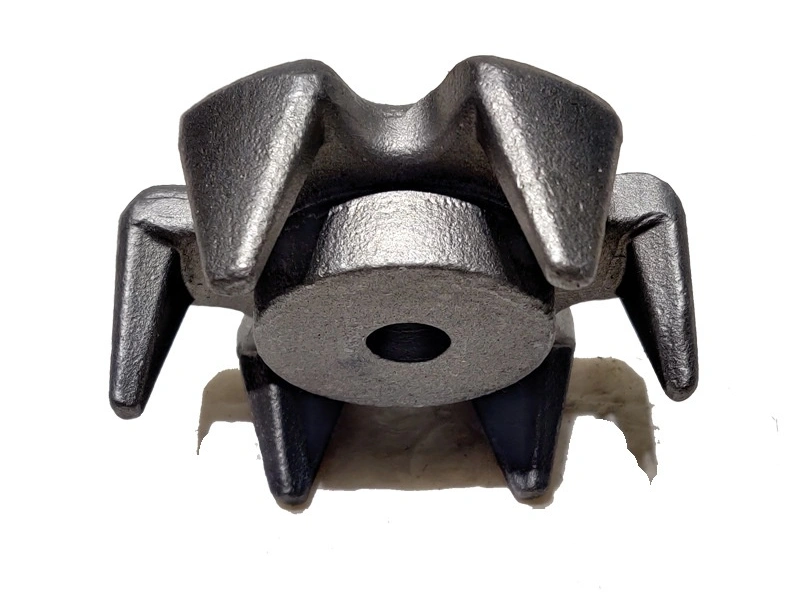
What Is Urethane Casting Prototyping?
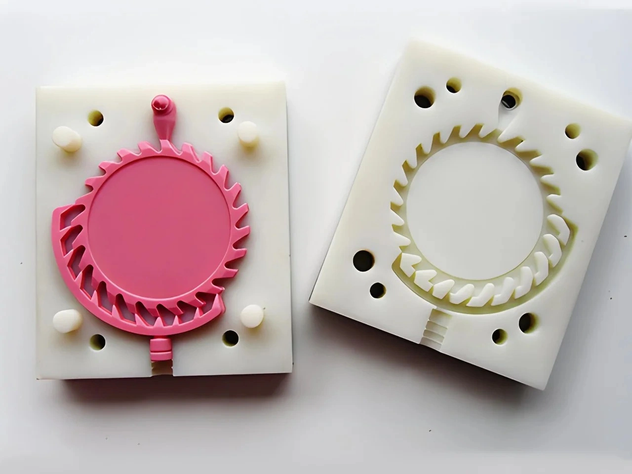
Urethane casting prototyping, often called polyurethane vacuum casting, is a soft-tooling process that reproduces a prepared master in a silicone mold using a two-component polyurethane system. The resin components are measured, mixed, degassed or cast under a controlled vacuum strategy, introduced into the mold, cured, demolded and trimmed. The process is used when a team needs several plastic-like parts from one controlled revision for assembly, appearance, ergonomic or bounded functional evaluation.
The process does not turn polyurethane into the specified production thermoplastic, and vacuum does not remove every defect automatically. Results depend on the master, mold split, resin selection, mix control, fill and vent plan, cure history, demolding, secondary work and inspection. A useful program therefore treats each stage as a release gate with traceable evidence rather than treating "vacuum cast" as a complete quality specification.
Urethane Casting Process at a Glance
| Stage | Controlled input | Main risk | Release evidence |
|---|---|---|---|
| Scope and DFM | CAD, drawing, revision, quantity, test intent and appearance zones | Prototype cannot answer the required decision | Requirement-to-evidence matrix and mold concept |
| Master pattern | Approved geometry, datum plan and surface standard | Every unwanted master defect transfers to the mold | Master inspection and appearance approval |
| Silicone mold | Split, cuts, cores, inserts, fill, vents and support | Tear, lock, flash, air trap or misalignment | Marked mold plan and first demolding review |
| Resin preparation | Identified system, ratio, batch, pigment and conditioning | Off-ratio mix, moisture, entrained air or early reaction | Batch record and material identification |
| Cast and cure | Sequence, vacuum/pressure practice, mold temperature and time | Short fill, bubbles, voids, cure variation or distortion | Process traveler and visual/internal checks as required |
| Finish and inspection | Trim map, secondary operations and acceptance plan | Witness damage, datum loss or cosmetic inconsistency | First-off report, approved sample and traceable lot |
Step 1: Define What the Prototype Must Prove
Before discussing resin or mold construction, define the next decision. A part for an assembly check needs controlled datums and real mating hardware. An appearance sample needs physical color, texture and viewing references. A grip study needs hardness variants and a user task. A duct or cover used in a functional screen needs the actual load, temperature, fluid, duration and pass criterion.
This first step prevents a common category error: asking a visually realistic polyurethane part to qualify production resin behavior. Urethane casting can close product-level questions under stated conditions, but it cannot create injection-molding evidence such as weld-line strength, fiber orientation, gate appearance, cooling distortion or ejection behavior. Mark those requirements as production-specific from the start.
Issue controlled CAD and a dimensioned drawing with one revision. Identify cosmetic faces, critical interfaces, permitted witness zones, inserts, required quantity by test and delivery lot, and the intended production process. The urethane casting design review can help expose missing information before a master is made.
Step 2: Build and Approve the Master Pattern
The master pattern is the physical source for the silicone cavity. Its geometry, repaired areas, edge condition and surface finish can appear in every subsequent casting. A master may be made by 3D printing, CNC machining, a hybrid route or another suitable pattern process. The choice depends on size, geometry, required surface, datum accessibility and the questions the prototype must answer.
A printed master can preserve organic forms and complex external geometry, but build orientation, support removal and surface preparation need review. A machined master can provide controlled accessible datums and faces, yet cutter access and corner radii may require a split or hybrid construction. Neither route guarantees the final mold surface without inspection and finishing.
Measure master features that drive fit or downstream inspection. For cosmetic work, approve the actual master surface or a representative area under defined lighting. Record any primer, paint, texture or repair that contributes to the mold. Fine lettering and sharp edges should be assessed for both replication and durability; a detail that appears once may not remain acceptable after repeated handling and demolding.
Step 3: Design the Silicone Mold
The master is positioned in a mold box, and liquid silicone is introduced around it according to the planned split and support arrangement. After cure, the mold is opened or cut and the master removed. The resulting cavity carries the inverse geometry and surface of the master. Depending on the part, the mold may include several pieces, loose cores, plugs, insert locators and external support.
Silicone compliance can release selected undercuts because the mold wall can peel and deform locally. Compliance is finite. Deep hooks, severe reverse geometry, thin silicone ligaments, fragile cast ribs and trapped cores can tear the mold or part. A planned knife cut may create an opening but also leaves a witness line and can generate flash as the cut wears or misaligns.
Review the mold as an operating system. Ask where it splits, how it is keyed, which direction each section is removed, what flexes during demolding, how loose cores are located and how the mold is supported during casting. Mark fill, vent and trim areas on the drawing. The silicone-versus-metal tooling comparison clarifies why a successful soft-tool release does not validate production draft or side actions.
Step 4: Select Polyurethane from the Test
Cast polyurethane systems can be selected across different stiffness, hardness, color, clarity and response ranges. Selection should start with the test condition, not a shorthand label such as "ABS-like," "PC-like" or "rubber-like." Those labels may describe one general attribute while obscuring differences in creep, impact mode, fatigue, chemical resistance, moisture response, thermal aging or fracture behavior.
For an assembly housing, stiffness and dimensional stability over the test period may matter. A grip study may prioritize hardness, friction and local section response. A transparent flow model may prioritize clarity and bubble control rather than long-term optical aging. A seal concept needs compression, recovery, fluid exposure and surface condition defined. One resin is unlikely to represent every property of the eventual material.
Ask for the material designation and available technical data, then state what the cast part must demonstrate. Use coupons or representative sections when a property decision cannot be isolated in the full part. Production qualification remains tied to the specified production material and process. This boundary is examined in the polyurethane material simulation guide.
Step 5: Condition, Measure and Mix the Resin
Two-component polyurethane chemistry depends on the supplier-defined component ratio and handling window. Components, pigments and the mold may need conditioning appropriate to the selected system. Moisture contamination can contribute to gas formation or surface defects in moisture-sensitive systems. Poorly dispersed pigment can create color variation; inaccurate proportioning can alter cure and part behavior.
The operator measures components, adds approved pigment or additives where applicable, and mixes them without losing control of the available working time. The batch record should identify material, lot or batch where required, mix ratio, pigment, date and part allocation. Exact process values belong to the selected material instructions and supplier procedure; they should not be replaced by one universal recipe.
A buyer does not need every proprietary shop parameter, but should require enough traceability to explain variation and reproduce an approved result. For comparison trials, do not mix unidentified materials or cure histories within one test population. Label samples so a failure can be traced to the physical part and process record.
Step 6: Use Vacuum and Pressure for Specific Defect Risks
Vacuum may be used during mixing, mold filling or both to reduce entrained air and help resin reach cavity features. Some workflows may use pressure after filling to reduce the visible size of remaining gas bubbles. The exact sequence depends on equipment, resin working time, mold geometry and defect risk. "Vacuum cast" does not mean the part is automatically void-free.
Air can remain at high points, blind pockets, texture or around inserts if there is no escape path. Resin can also react or thicken before a remote thin section fills. Excessive or poorly controlled vacuum can create its own process problems depending on the material. Mold leakage and inadequate support can affect fill and geometry.
Review fill and vent locations before molding, especially for clear parts, thin remote features and enclosed channels. Use visual inspection, transmitted light, sectioning or another suitable method where internal quality affects the test. Inspection intensity should match consequence: a cosmetic bubble, a blocked fluid path and a void beside a loaded insert are different risks.
Step 7: Cure, Post-Cure and Condition
After filling, the polyurethane reacts and develops enough integrity for demolding. Some systems or test requirements may use a defined post-cure or conditioning period. Cure state affects handling, dimensions and mechanical response. Demolding too early can distort the part; measuring or testing at inconsistent ages can make samples appear more variable than they are.
Record the relevant cure and conditioning history for parts used in quantitative comparison. State when dimensions will be measured and when functional testing begins. Flexible sections, moisture-sensitive materials and elevated-temperature tests deserve particular attention. The supplier should confirm the procedure against the selected resin instructions and part section, rather than applying a fixed time to every project.
Step 8: Demold Without Hiding Damage
Demolding usually involves opening the mold and peeling silicone away from the cured part. The operator may remove loose cores or plugs in a planned sequence. Release force concentrates around undercuts, texture, deep draw and thin details. Both mold and part should be inspected after the first release and periodically during the build.
Look for incipient silicone tears, permanent stretch, cut-edge damage, distorted keys, part cracks, bent hooks and surface scuffing. A casting that looks acceptable externally may have been overstressed during removal. If a functional feature repeatedly damages the mold, revise the split, core, release sequence or geometry rather than relying on a nominal mold-output number.
Silicone mold output is an acceptance question, not a fixed shot count. Useful life ends when the mold no longer produces parts that meet the agreed dimensional, cosmetic and functional criteria. Geometry, resin chemistry, cure heat, surface area, demolding strain, cuts, maintenance and storage all influence that point.
Step 9: Trim, Finish and Add Secondary Features
Cast parts need gate and vent removal, flash trimming and cleaning. They may also receive sanding, painting, polishing, masking, bonding, insert installation or limited machining. These operations can make a prototype usable and visually coherent, but they also add variation and cost. A repaired show sample is not the same delivered state as an as-cast engineering sample.
Put trim boundaries and acceptable witness areas on the drawing. Protect datums and sealing faces during finishing. If holes, threads or mating faces are machined after casting, identify which dimensions are controlled by the mold and which by the secondary setup. For inserts, define position and the actual pull, torque or load criterion. The secondary-feature planning FAQ helps buyers avoid unspecified hand work.
Step 10: Approve the First-Off and Control the Build
A first-off sample should be checked before the full build proceeds. Confirm identity, revision, material, key dimensions, assembly, appearance, parting and cut witness, trim, insert position and obvious casting defects. Preserve an approved appearance sample where finish matters. If the first-off fails, identify whether the source is master, mold, casting, cure, demolding or finishing before remaking parts.
Not every drawing dimension needs the same inspection frequency. Classify characteristics by test consequence and process risk. Use gauges or mating checks where they answer the decision more directly than a broad dimensional report. Track mold/cavity and cast sequence for characteristics likely to drift with mold condition. Packaging should prevent flexible parts taking a set and cosmetic surfaces rubbing during shipment.
Urethane casting accuracy should be discussed feature by feature. Master error, silicone deformation, resin response, support, part geometry and measurement condition all contribute. A supplier capability statement cannot replace inspection of the actual geometry at the accepted state.
Diagnose Defects by Process Stage
Defect names alone do not identify corrective action. A bubble may come from entrained air, a blind pocket, moisture-sensitive chemistry or leakage at an insert. Short fill may point to working time, flow restriction or an inadequate vent. Flash can come from a worn cut, poor mold closure or unsupported silicone. Dimensional mismatch may begin in the master, mold alignment, casting support, cure or measurement condition.
When a first-off fails, preserve the part and inspect the mold before making another casting. Record the defect location relative to fill, vents, cuts, cores and section changes. Use sectioning, transmitted light, a mating check or dimensional trend only when it can distinguish likely causes. Correct the source stage, then document the changed mold or process condition so the next sample is not compared as though nothing changed.
Sample allocation should anticipate this diagnostic work. Reserve sacrificial parts for sections or destructive interface tests, retain an untouched appearance standard and keep enough controlled samples for repeat measurements. A build that consumes every part in stakeholder demonstrations leaves no evidence for resolving a later defect or production handoff question.
What the Process Can and Cannot Validate
Urethane prototypes can support envelope, assembly access, mating checks, handling, ergonomic feedback, selected material-response screens, appearance targets and some insert or interface tests. Several controlled parts allow parallel reviews and limited repeatability observations. Those are meaningful development outputs when linked to sample IDs and acceptance records.
They cannot qualify an injection-molded thermoplastic or die-cast alloy. They do not prove production gates, runners, vents, cooling, ejection, molded fiber orientation, cycle time, rate or yield. Silicone mold flexibility may release geometry that a rigid production tool needs to redesign. A polyurethane sample also cannot establish regulatory compliance or service life for an unspecified production material.
Before production tooling, create an evidence-transfer register. Mark each requirement as closed by the prototype, informed but still open, or production-specific. Carry open items into production DFM, material qualification, tool sampling and process validation. The production-tooling evidence guide describes that handoff in detail.
When Urethane Casting Is the Wrong Definition of the Job
A one-off changing concept may be more direct to print. Exact stock material and accessible precision features may favor CNC. Tests of production resin flow, adhesion, weld lines or molding behavior need injection-molded samples. Metal thermal conductivity, stiffness or structural behavior requires an appropriate metal prototype or production-intent process rather than a painted polyurethane shape.
The process may also become unattractive when recurring demand, cadence, manual finishing or repeated mold replacement dominates total cost. There is no universal transition quantity. Compare cumulative delivered states across demand and revision scenarios, including tooling, sampling, inspection, finish, packaging and change exposure.
RFQ Inputs and Release Gates
A quote-ready RFQ should include:
- Controlled 3D CAD and a dimensioned drawing with one revision identifier.
- The decision each sample must support and the acceptance criteria for that decision.
- Quantity by test, variant and delivery lot, plus expected replenishment cadence.
- Production material and process for context, separated from the cast property target.
- Critical dimensions, datums, mating parts, gauge or measurement method and conditioning state.
- Cosmetic faces, physical color/texture standards, viewing conditions and permitted witness areas.
- Insert, thread, machining, bonding and assembly requirements with functional loads.
- Temperature, fluid, UV, impact, cycle or other exposures and their pass/fail criteria.
- Material records, inspection, traceability, labeling, packaging and retained-sample needs.
Release the program in stages: scope and evidence matrix, master approval, mold plan, material/process record, first-off approval, build inspection and evidence transfer. The cast urethane RFQ checklist provides a compact input review.
That is what urethane casting prototyping is in engineering terms: a controlled reproduction route using a master, silicone tool and reactive polyurethane to create several development parts. Its value does not come from resemblance alone. It comes from knowing which variables were controlled, which requirements were tested and which production questions remain open.
FAQs